TB-9-2300-403-45 - Page 1 of 5
* TB 9-2300-403-45
DEPARTMENT OF THE ARMY TECHNICAL BULLETI N
CONTINENTAL MODELS AV-1790 AND AO-895 AND
GMC MODELS 6V53/6V53T AND 8V71T SERIES ENGINES:
REPAIR OF ALUMINUM OIL COOLERS
Headquarters, Department of the Army, Washington, D. C.,
15
March 1971
1. Purpose.
This bulletin provides general support,
depot, and contractor maintenance personnel with
instructions for repair of aluminum oil coolers by
welding or brazing.
2. Scope.
This bulletin applies to all GS, depot, and
contractor repair of Continental Model AV-1790
and AO-895 and GMC 6V53/6V53T and 8V71T engines.
3. Equipment required.
a.
Arc welding machine
for inert gas shielded tungsten arc (Heliarc, Argon-
arc) or inert gas shielded metal arc consuming
electrode process.
b.
Class 4043 electrode, conforming to specifica-
tion QQ-R-556A or MIL-E-16053.
c.
ALCOA No. 33 torch brazing flux or equivalent.
d.
ALCOA No. 718 or 716 brazing alloy or equiva-
lent,
1/16
and l/8-inch diameter.
4. Repair Procedure.
a.
Degrease coolers, using
vapor or liquid solvents. Dry with compressed air.
WARNING
Degrease vapors may produce phosgene gas.
Do not place coolers into alkali strip tanks.
b.
Prepare surface by removing all foreign matter
from area to be welded by use of stainless steel wire
brush, drill, burring tool, approved chemical proc-
ess, or steam cleaning.
c.
Preparation of cracks, fractures, and areas
having metal missing:
(1) Use dye method to determine length of
crack, if not visible.
(2) Drill 3/16-inch stop holes at ends of the crack
or fracture.
(3) Mill or grind out cracks to provide a “V”
aperture.
*This Bulletin supersedes TB 9-288, 10 November 1959.
d.
Housing welding procedure.
CAUTION
Use extreme care in welding aluminum cool-
ers to prevent damage to fins and tubes.
Refer to TM 9-237 for preliminary instruc-
tions on welding of aluminum.
NOTE
An interpass temperature of 250° F to 395° F,
measured two inches from the weld, will be
maintained until the joint is completely
welded.
(1) When preheat temperature of 350° F plus or
minus 35 F has been reached, position housing in
the most advantageous welding position. Cover all
but the area to be repaired with asbestos blankets
to maintain heat.
(2) Weld the milled groove, assuring a good
root weld; then, apply fillet welds until groove
is filled and closed.
(3) Remove blankets and allow to cool to room
temperature.
e.
Machine the repaired surfaces back to original
configuration. Repaired bolt holes must be proper-
ly located, drilled, and threaded to original size and
thread pitch.
f.
Replacement of Header Tube:
(1) Clean in accordance with
a
above.
(2) Plug all parts to prevent entrance of con-
taminants.
(3) Saw-cut each end of header tank.
(4) Saw-cut each end of tube for removal.
(5) Remove remainder of tube by reaming.
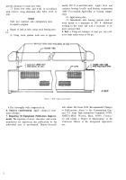
(6) Saw-cut one end, as shown in Figure 1, to
1
Back to Top


