TM-9-2330-356-14
SEMITRAILER, TANK: 5000 GALLON, BULK HAUL, SELF LOAD/UNLOAD M967 AND M967A1; SEMITRAILER, TANK: 5000 GALLON, FUEL DISPENSING, AUTOMOTIVE M969 AND M969A1; SEMITRAILER, TANK: 5000 GALLON, FUEL DISPENSING, UNDER/OVERWING AIRCRAFT M970 AND M970A1
TECHNICAL MANUAL; OPERATOR’S, UNIT, DIRECT SUPPORT, AND GENERAL SUPPORT MAINTENANCE MANUAL
OCTOBER 1990
TM-9-2330-356-14 - Page 192 of 528
TM 9-2330-356-14
(2)
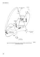
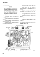
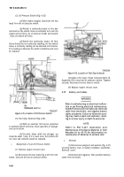
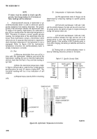
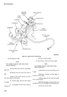
Oil Pressure Switch (Fig. 4-35).
(a)
With engine stopped, disconnect the two
leads from the oil pressure switch.
(b)
Attach a continuity tester to the two
terminals on the switch. Have an assistant turn over the
engine several times. As oil pressure builds and exceeds
13 psi, the switch will close.
(c)
Watch the continuity tester. At first
there should be no continuity reading. As the switch
closes, a continuity reading can be observed on the tester.
If no reading is obtained, the switch is defective and must
be replaced.
TA502347
Figure 4-35. Location of Oil Pressure Switch.
(3)
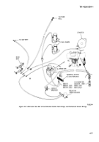
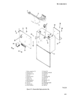
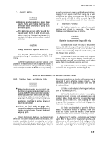
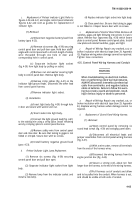
Fuel Stop Solenoid (Fig 4-36).
(a)
With an external 12V source connected
to solenoid switch terminal, check operation of plunger
and current draw.
(b)
Current draw with the plunger up
should be about 1 amp. If it is much more, the contacts did
not close and solenoid should be replaced.
c.
Replacement of Low Oil Pressure Switch.
(1) Remove engine shroud cover.
(2) Disconnect the two leads (fig. 4-35) from the
switch. Unscrew the low oil pressure switch.
TA502348
Figure 4-36. Location of Fuel Stop Solenoid.
(3) Apply a thin layer of pipe compound (item 26,
Appendix E) to new low oil pressure switch. Tighten
securely. Reconnect the two leads to switch.
(4) Replace engine shroud cover.
4-23.
Battery and Cables
WARNING
When troubleshooting an electrical malfunc-
tion or performing electrical maintenance,
ALWAYS disconnect Intervehicular electrical
cable from semitrailer, and negative battery
cables at batteries. Failure to follow this warn-
ing may create a spark and explosion, result-
ing in serious injury or death to personnel.
NOTE
Refer to FM 9-207, Operation and
Maintenance of Ordnance Material in Cold
Weather (0° to -65 ‘F) for Information on
maintenance of batteries In extreme cold.
a.
Removal.
(1) Remove two wingnuts and washers (fig. 4-37)
securing battery cover to battery holddown assemblies.
Remove cover.
(2) Disconnect negative, then positive battery
cables from terminals.
4-56
Back to Top

