TM-9-2330-356-14
SEMITRAILER, TANK: 5000 GALLON, BULK HAUL, SELF LOAD/UNLOAD M967 AND M967A1; SEMITRAILER, TANK: 5000 GALLON, FUEL DISPENSING, AUTOMOTIVE M969 AND M969A1; SEMITRAILER, TANK: 5000 GALLON, FUEL DISPENSING, UNDER/OVERWING AIRCRAFT M970 AND M970A1
TECHNICAL MANUAL; OPERATOR’S, UNIT, DIRECT SUPPORT, AND GENERAL SUPPORT MAINTENANCE MANUAL
OCTOBER 1990
TM-9-2330-356-14 - Page 214 of 528
TM 9-2330-356-14
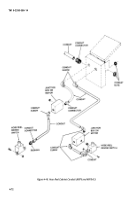
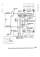
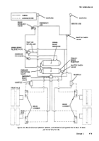
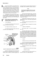
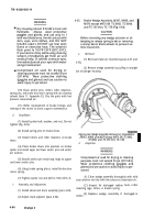
Figure 4-56. Brake-Interlock (M970 and M970A1).
(3) A
fill valve is installed on the roadside of the
semitrailer to permit filling of the front reservoir
(pars 2-4).
d,
Service Brake. When
the towing vehicle is
attached the foot brake operates the brakes on both the
semitrailer and the towing vehicle.
(1) Applying the brake pedal delivers air through
the service line to the emergency relay valve.
(2) In response to the service signal, the
emergency relay valve releases air from the rear reservoir
to the brake chambers. Air pressure causes the camshaft
in each brake assembly to rotate and force the broke shoes
against the brake drum.
(3) Releasing the brake pedal stops the service
signal to the emergency relay valve. The emergency relay
valve closes the supply from the reservoir and releases air
from the brake chambers.
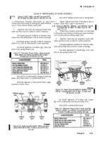
e. Emergency Relay Valve (Fig. 4-54). This valve
increases the speed at which the brakes apply and release.
The relay valve is attached to the rear reservoir above the
forward axle.
(1) The emergency relay valve releases air from
the rear (primary) reservoir to all brake chambers in
response to the service signal from the towing vehicle.
(2) The emergency relay valve will also cause the
fail-safe brakes to apply automatically if the semitrailer
breaks away from the towing vehicle.
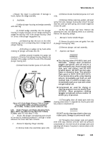
f
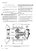
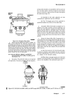
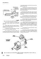
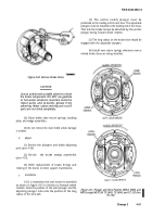
Fail-Safe Units (Fig.
4-57). The fail-safe units are
spring chambers which are assembled piggyback on the
brake air chambers. One each is installed on the air
chambers at the four comers of the tandem axle assembly.
The fail-safe unit provides parking and emergency
braking.
(1) Air pressure of
approximately 65psi is needed
to release the fail-safe units.
(2) Loss
of air pressure will release the heavy
spring and push the piston against the diaphragm plate of
the air chamber. This force is applied through the
camshaft to the brake shoes.
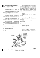
Figure 4-57. Brake Actuator Assembly (M967A1, M969A1, and M970A1 including M970 SN TC-0843, TC-0844, and
TC-103 thru TC-178).
4-78
Change 3
Back to Top

