TM-9-2330-356-14
SEMITRAILER, TANK: 5000 GALLON, BULK HAUL, SELF LOAD/UNLOAD M967 AND M967A1; SEMITRAILER, TANK: 5000 GALLON, FUEL DISPENSING, AUTOMOTIVE M969 AND M969A1; SEMITRAILER, TANK: 5000 GALLON, FUEL DISPENSING, UNDER/OVERWING AIRCRAFT M970 AND M970A1
TECHNICAL MANUAL; OPERATOR’S, UNIT, DIRECT SUPPORT, AND GENERAL SUPPORT MAINTENANCE MANUAL
OCTOBER 1990
TM-9-2330-356-14 - Page 216 of 528
TM 9-2330-356-14
g.
Brake Interlock (M970A1 including M970 SN TC-
0843, TC-0844, and TC-103 thru TC-178).
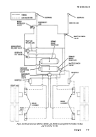
The brake interlock
system is activated when the door on the hose reel cabinet is
open. When actuated, the interlock valve sends air from the
rear reservoir into the service air line. This gives a service
signal to the emergency brake relay valve. The relay valve
releases air from the rear reservoir to the brake air chambers to
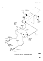
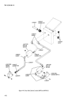
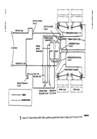
apply the brakes. Figures 4-56 and 4-58 show how the
interlock system connects into the air brake system
h.
Slack Adjusters.
These convert linear motion of
the brake chamber to rotating motion of the camshaft.
The slack adjuster consists of a housing, two gears, and
two gear covers. Brake adjustments are made through the
slack adjuster.
4-33.
Service Brake Shoe Assemblies, M967,
M969, and M970 except M970 SN TC-0843,
TC-0844, andTC-103 thru TC-178.
a.
Test and Adjustment.
(1)
the ground.
(2)
(3)
and bottom
Jack up the semitrailer and lift all wheels off
Block the frame securely.
Release the fail-safe units (pars 2-4).
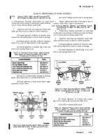
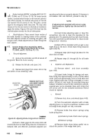
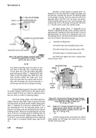
Remove dust plugs from access slots at top
of dust shield (fig. 4-59).
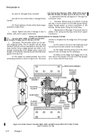
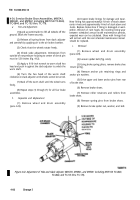
Figure
4-59.
Adjusting Brake Lining-to-Drum Clearance.
(4) Insert a feeler gage into the access slots and
check brake drum to brake lining clearance. If clearance is
between .040- and .060-inch, automatic adjusters are
operating and brakes are properly adjusted. If clearance is
not between .040- and .060-inch, proceed to step (5).
NOTE
If adjusting bolt starwheel will not turn using
hand pressure, lightly tap the tool with a
hammer.
(5) Insert brake adjusting spoon or long thin
screwdriver into slot to meet the starwheel on the
adjusting bolt. The adjusting bolt has right hand threads.
Turn the starwheel counterclockwise to reduce brake
lining-to-drum clearance.
(6) Back off the starwheel until you get a very
slight drag on the drum. Check brake lining clearance
again (step (4)).
(7) Repeat steps (4) through (6) above for the
other shoe on brake.
(8) Repeat steps (1) through (6) for all brake
assemblies.
b.
Inspection and Replacement.
(1) Remove wheel
and drum assembly
(pars 4-49).
(2) Inspect brake linings for damage and wear.
New lining has approximately ½-inch of stock above
center rivets and approximately ¼-inch of stock above end
rivets. Replace brake shoe if lining is damaged or is worn
within .030-inch of rivet heads. By recording lining wear
between scheduled annual brake maintenance periods,
expected wear can be calculated. Shoes with linings that
will not last until the next scheduled maintenance internal
should be replaced.
c.
Removal.
(1) Remove hub, drum, and wheels (para 4-49).
(2) Turn the automatic adjusters with a brake
adjusting spoon or a long thin screwdriver clockwise until
the wedge brake plungers are fully contracted.
(3) Remove brake shoe return springs using
brake spring pliers.
(a)
Unhook top hook of both return springs.
(b)
Remove springs.
(4)
Remove brake shoes being careful not to
disturb the position of the wedge brake parts.
4-80
Change 3
Back to Top

