TM-9-2330-356-14
SEMITRAILER, TANK: 5000 GALLON, BULK HAUL, SELF LOAD/UNLOAD M967 AND M967A1; SEMITRAILER, TANK: 5000 GALLON, FUEL DISPENSING, AUTOMOTIVE M969 AND M969A1; SEMITRAILER, TANK: 5000 GALLON, FUEL DISPENSING, UNDER/OVERWING AIRCRAFT M970 AND M970A1
TECHNICAL MANUAL; OPERATOR’S, UNIT, DIRECT SUPPORT, AND GENERAL SUPPORT MAINTENANCE MANUAL
OCTOBER 1990
TM-9-2330-356-14 - Page 218 of 528
TM 9-2330-356-14
4-34. Service Brake Shoe Assemblies, M987A1,
M969A1, and M970A1 including M970 SN TC-0843,
TC-0844, and TC-103 thru TC-178.
a
Test and Adjustment.
(1) Jack up semitrailer to lift all wheels off the
ground. Block the frame securely.
(2) Release all spring forces from slack adjuster
and camshaft by applying air to the air brake chamber.
(3) Check that the wheels rotate freely.
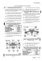
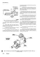
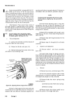
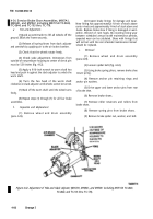
(4) Check yoke adjustment. Dimension from
outside of nonpressure housing to center of clevis pin
must be 5.56-inches (fig. 4-62).
(5) Apply a 9/16-inch wrench to worm shaft hex
head and push in against the slack adjuster to unlock the
worm shaft.
(6) Turn the hex head of the worm shaft
clockwise on slack adjuster until wheels cannot be turned.
(7) Back off the worm shaft until the wheel turns
freely.
(8) Repeat steps (1) through (7) for all four brake
assemblies.
b.
Inspection and Replacement.
(1) Remove wheel and drum assembly
(para 4-49).
(2) Inspect brake linings for damage and wear.
New lining has approximately) ½-inch of stock above
center rivets and approximately ¼-inch of stock above end
rivets. Replace brake shoe if lining is damaged or worn
within .030-inch of rivet heads. By recording lining wear
between scheduled annual brake maintenance periods,
expected wear can be calculated. Shoes with linings that
will not last until the next scheduled maintenance interval
should be replaced.
c.
Removal.
(1) Remove wheel and drum assembly
(para 4-49).
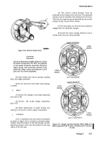
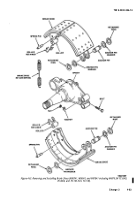
(2) Loosen spider bolt (fig. 4-63).
(3) Using broke spring pliers, remove broke shoe
return spring.
(4) Remove anchor pin retaining rings and
anchor pin washers.
(5) Drive upper and lower anchor pins from rear
of brake shoe.
(6) Remove brake shoes.
(7) Remove roller retainers and rollers from
brake shoes.
(8) Remove spring pins from brake shoes.
(9) Remove brake spider nut, washer, and bolt.
Figure 4-62. Adjustment of Yoke and Slack Adjuster (M967A1, M969A1, and M970A1 including M970 SN TC-0843,
TC-0844,
and TC-103 thru TC-178).
4-82
Change
3
Back to Top

