TM-9-2330-356-14
SEMITRAILER, TANK: 5000 GALLON, BULK HAUL, SELF LOAD/UNLOAD M967 AND M967A1; SEMITRAILER, TANK: 5000 GALLON, FUEL DISPENSING, AUTOMOTIVE M969 AND M969A1; SEMITRAILER, TANK: 5000 GALLON, FUEL DISPENSING, UNDER/OVERWING AIRCRAFT M970 AND M970A1
TECHNICAL MANUAL; OPERATOR’S, UNIT, DIRECT SUPPORT, AND GENERAL SUPPORT MAINTENANCE MANUAL
OCTOBER 1990
TM-9-2330-356-14 - Page 221 of 528
TM 9-2330-356-14
c.
Repair. No repair is authorized. If damage is
found, replace the wedge assembly.
d.
Installation.
(1) Wipe plunger housing and wedge assembly
with clean rag.
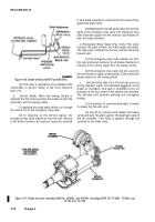
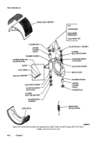
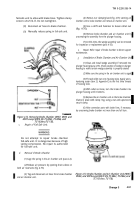
(2) Install wedge assembly into the plunger
housing. It maybe necessary to turn wedge assembly to
engage the tabs (fig. 4-65) in the plunger housing. Check
for correct roller-plunger engagement by:
(a)
Observing that the ears on the roller
retaining cage are in corresponding slots in wedge bore of
plunger housing.
(b)
Pushing on wedge rod by hand while
checking for plunger and brake shoe lift.
d.
(c)
When properly installed, the wedge rod
standout is 2¼-inches from plunger housing. Measure the
standout of the wedge rod from the end of the threaded
plunger housing bore.
(3) Install brake chamber (paras 4-37 and 4-39).
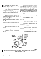
Figure 4-65. Brake Wedge Alinement Tabs in Plunger
Housing (M967, M969, and M970 except M970
SN TC-0843, TC-0844, andTC-103thruTC-178).
4-36.
Brake Plungers and Brake Adjusting Parts,
M967, M969, and M970 except M970 SN TC-0843,
TC0844, and TC-103 thru T-178.
a.
Service. The
plungers and adjusting parts should
be serviced by following procedures c through e below
whenever the shoes have been removed.
b.
Removal of Adjusting Plunger Assembly.
(1) Remove brake shoe assemblies (para 4-33).
(2) Remove brake chamber(s) (paras 4-37 and
4-39).
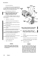
(3) Remove hollow capscrew, gasket, and pawl
spring from side of plunger housing (fig. 4-66). If the pawl
does not come out with spring, use a small magnet to
remove the pawl.
(4) Pry the plunger seal loose. Remove the
adjusting bolt, seal, and adjusting sleeve as an assembly.
Remove the adjusting plunger.
c.
Removal of Anchor (Solid) Plunger.
(1) Remove the guide screw and gasket from side
of plunger housing (fig. 4-66).
(2) Remove plunger and seal assembly.
Inspection and Repair.
WARNING
Dry cleaning solvent P-D-680 Is toxic and
flammable.
Always wear protective
goggles and gloves, and use only In a
well-ventilated area. Avoid contact with
skin, eyes, and clothes, and DO NOT
breathe vapors. DO NOT use near open
flame or excessive heat. The solvent’s
flash point is 100°F-138°F (38°C-59°C).
If you become dizzy while using cleaning
solvent, Immediately get fresh air and
medical help. If solvent contacts eyes,
immediately wash your eyes with water
and get medical aid.
Compressed air used for drying or
cleaning purposes must not exceed 30 psi
(207 kPa).
Wear protective clothing
(goggles and gloves) and use caution to
avoid injury to personnel.
(1) Thoroughly clean all metal parts with dry
cleaning solvent (item 11, Appendix E). Dry the parts with
low pressure compressed air.
CAUTION
DO NOT use dry cleaning solvent to clean any
rubber parts. Damage to parts would result.
(2) Thoroughly clean plunger seals and gaskets
with mild soap solution and dry with low pressure
compressed air. Use wire brush on plunger parts and
adjusting bolt threads, if required, to remove caked on dirt
and corrosion.
Change 3
4-85
Back to Top

