TM-9-2330-356-14
SEMITRAILER, TANK: 5000 GALLON, BULK HAUL, SELF LOAD/UNLOAD M967 AND M967A1; SEMITRAILER, TANK: 5000 GALLON, FUEL DISPENSING, AUTOMOTIVE M969 AND M969A1; SEMITRAILER, TANK: 5000 GALLON, FUEL DISPENSING, UNDER/OVERWING AIRCRAFT M970 AND M970A1
TECHNICAL MANUAL; OPERATOR’S, UNIT, DIRECT SUPPORT, AND GENERAL SUPPORT MAINTENANCE MANUAL
OCTOBER 1990
TM-9-2330-356-14 - Page 223 of 528
TM 9-2330-356-14
(3) Inspect plunger seals and gaskets for damage,
cuts, or deterioration.
(4) Inspect plungers for rust, nicks, pits, or
grooves.
(5) Check for burrs on nose of anchor plunger.
Remove burrs with a fine file or crocus cloth. A bright,
shiny surface where wedge roller contacts the plunger
surface is normal.
(6) Check threads of adjusting bolt for damage.
(7) Replace all parts which are not in good
condition.
e.
Installation of Anchor (Solid) Plunger.
CAUTION
DO NOT assemble seals Into plunger housing
first. This will result in complete lack of seal-
ing of Internal plunger housing components.
NOTE
Each plunger housing assembly has
one
ad-
justing plunger and one anchor (solid) plung-
er. The
l
nchor plunger Is marked on the
slotted end, “R” for right-hand brakes and “L”
for left-hand brakes. DO NOT mix at assem-
bly.
(1) The anchor plunger and seal is serviced as an
assembly. Refer seal replacement to direct support
maintenance.
(2) Install plunger and seal assembly into plunger
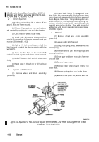
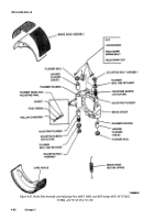
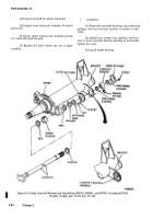
housing in the following manner (fig. 4-66).
(a)
Coat plunger bore with grease (item 17,
Appendix E).
(b)
Coat entire plunger with grease (item
17, Appendix E). AIso pack the cavity behind the seal
assembly.
(c)
Insert plunger and seal assembly into
housing with plunger keyway slot alined with guide hole in
plunger housing. The plunger must go all the way into the
plunger bore and seat on the bosses at bottom of the
plunger housing.
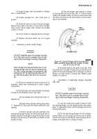
(d)
Seat the plunger seal assembly in plung-
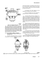
er housing with seal driver (fig. 4-67). A 1¾-inch wrench
socket and rawhide mallet can also be used. Ensure that
the seal is centered over the seal retainer to prevent dam-
age to seal assembly.
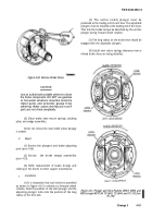
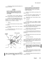
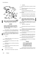
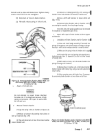
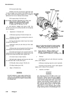
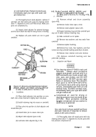
Figure 4-67. Seating Plunger Seal in Housing (M967,
M969, and M970 except M970 SN TC-0843, TC-0844.
and TC-103 thru TC-178).
(3) Assemble gasket and guide screw (fig. 4-66)
into guide hole in plunger housing. Ensure that the end of
guide screw enters keyway slot in plunger so anchor
plunger can slide freely in housing
bore.
Tighten guide
screw to 15-20lb.-ft.
f.
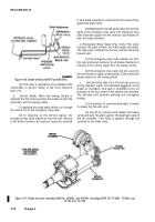
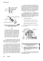
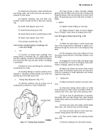
Installation of Adjusting Plunger Assembly
(Fig. 4-68).
CAUTION
DO NOT assemble seals Into plunger housing
first. This will result In complete lack of seal-
ing of Internal plunger housing components.
(1) Coat the inside and outside surfaces of both
the adjusting plunger and the adjusting sleeve with grease
(item 17, Appendix E). Also coat the plunger bore in the
housing with grease.
(2)
Put the adjusting plunger into the plunger
housing. Make sure the plunger goes all the way to bottom
of bore and seats on the bosses. Aline keyway slot in
plunger with guide hole in plunger housing.
Change 3
4-87
Back to Top

