TM-5-3895-372-10 - Page 11 of 184
TM 5-3895-372-10
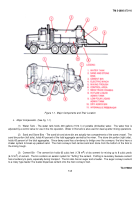
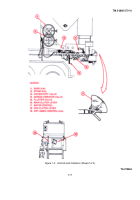
(4) Electric Winch - The electric winch raises and lowers the mixing trough, and supports it during cement
production.
(5) Mixing Trough - The mixing trough mixes dry and wet ingredients (sand, stone, cement, water and
admixtures).
They are mixed into concrete by an auger located in the trough.
The auger also conveys the mixed concrete
to the chute for placement
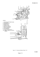
(6) Control Area - Mixer controls are clustered at the left rear of the unit. This allows the operator to see the
mixing process as he runs the machine.
From the control area the operator can adjust ingredient proportions, position the
mixing trough, and start or stop the mixing operation.
(7) M919 Truck Chassis - The mixer body is mounted on an M919 truck chassis.
The mixer unit is powered by
the truck engine. For more information, see TM 9-2320-273-10.
(8) Hi-Flow Liquid Admix Tank - The hi-flow admix tank holds 42 gallons (159 1) of admixture solution for
injection into the mix.
(9) Low-Flow Liquid Admix Tank- The low-flow admix tank holds 12 gallons (45 I1) of admixture solution for
injection into the mix This tank serves the same purpose as the Hi-Flow tank but is used when smaller quantities of
admixture are needed.
(10) Dry Admix Bin - The dry admix bin holds 2.35 cubic feet (0.66 m
3
) of powdered admixture.
Augers in the
bin guide the powder into a feeder shaft.
The feeder delivers the admixture to the main conveyor belt.
The dial setting on
the bin determines the delivery rate.
(11) Hydraulic Reservoir - Stores 32 gallons of hydraulic fluid to operate the hydraulic system.
d. Functional Description.
The cement meter-feeder dispenses cement from the cement bin at a constant rate.
Each mixer is calibrated at the factory and settings are provided on a permanent plate in the control area.
To produce
different types of concrete, you will vary the amounts of sand, stone, water and admix which are added to the cement.
(1) Sand delivery is controlled by a gate limiting the amount of sand carried out of the bin by the main conveyor
belt.
(2) Stone delivery is controlled by a similar gate mounted on the rear of the stone bin.
(3) Water proportions are adjusted by the water control. A dial mounted on the valve helps you set the flow.
(4) Liquid admix flow rates are set by a pair of flowmeters (one for each tank). Flow is adjusted with a lever.
(5) Dry admix metering is controlled by a dial setting on the bin.
(6) When the PTO is engaged, power is supplied through a belt-driven shaft to the water pump and hydraulic
pump.
When the main clutch is engaged, the belt-driven shaft also turns the main conveyor belt.
If the cement and dry
admix clutches are engaged, the cement and dry admix feeders will turn along with the main conveyor. The main clutch
lever is mechanically linked to valves which open the water and liquid admix lines.
Thus, engaging the main clutch starts
delivery of all ingredients The main conveyor dumps dry ingredients into the mixing trough, where the water and liquid
admix are added.
The hydraulically powered auger in the trough mixes the ingredients as it pushes them to the delivery
chutes. These removable chutes guide the wet concrete into place.
1-3
Back to Top


