TM-55-1425-289-14
TM-55-1425-289-14 - Page 51 of 61
TM 55-1425-289-14
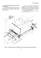
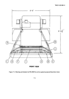
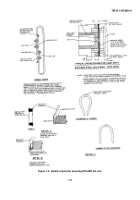
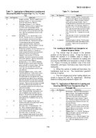
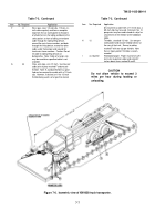
Table 7-1.
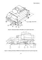
Application of Materials for Loading and
Securing ROLAND Fire Unit (Figs 7-2, 7-3, 7-4, and
7-5)
Item
No. Required
Application
A
4
Support assembly.
See the "support assem-
bly detail in figure 7-4.
Nail the assembly
to the car floor with four 16d nails.
B
4
Pallet beam stiffeners, 2- x 6- x 48-inch
(doubled).
Position so that it is approximate-
ly 2 inches from contacting the lateral
stiffener on the underside of the pallet.
Nail
the first piece to the car floor with seven 20d
nails.
Nail the second piece to the first with
seven 50d nails.
C
8 each
Side blocks, 2- x 6- x 42-inch and 2- x 8- x
42-inch.
Position the first 2- x 6-inch piece
next to the pallet, and nail to the car floor
with eleven 20d nails.
Position the second 2-
x 6-inch piece on top of the first piece
(against pallet beam web), and nail the
eleven 20d nails.
Nail the second 2- x 8-inch
piece to the first in a like manner.
D
2
Knee brace assembly.
See the "knee brace as-
sembly" detail in figure 7-4.
Position as
shown, on top of the pallet transverse beam,
centered on the fire-unit module hull.
E
2
Headers, 2-inch x 6-inch x 7-ft 0-inch
(doubled).
Nail the first piece to the car floor
with sixteen 20d nails.
Nail the second piece
to the first with sixteen 50d nails.
F
8
Backup cleats, 2- x 6- x 36-inch (doubled).
Position two cleats side by side to align with
piece marked D, as shown in figure.
Nail the
first piece to the car floor with nine 20d
nails.
Nail the second piece to the first with
nine 50d nails.
G
4
Dunnage holddown straps, 2-inch x .050-
inch by length-to-suit.
Install to form a com-
plete loop over the knee brace assembly.
Thread through the stake pocket from inside
to outside on each side of the car and bring
both ends up above the knee brace assembly,
where they can be tensioned and sealed with
two seals.
Secure to the knee brace assembly
with the two 20d nails driven partially into
the assembly and bent over the strap at each
end of the assembly.
H
8
Pads, steel, strapping, 2-inch x .050-inch
long.
Position pad under stake pocket, and
seal to holddown strap marked G (fig 7-5,
detail A).
For alternate stake pocket protec-
tor (16 required), use two pads under each
stake pocket with a holddown strap (see fig
7-5, detail A).
I
16
Seals, 2-inch strapping, four per strap.
Double-crimp each seal except those used to
secure the pads marked H.
J
2
Wire rope, steel, 112-inch-diameter, 11.5-
ton.
Form a complete loop through a car
stake pocket and around the tiedown facility
at the forward end of the lading.
K
1
Wire rope, steel, 112-inch dia, 11.5-ton.
Form a complete loop through the car stake
pockets and the aft end of the cable facilities
as shown in figure 7-5.
Table 7-1.
Continued
Item
No. Required
Application
L
6
Thimble, standard, 1/2-inch.
Use one each
for the car stake pocket and the forward end
tiedown facility.
Secure to cables marked J
and K with one clip per thimble.
Note: A
standard thimble as specified can be secured
to a cable with a 11/2-inch clip.
However, if
desired, or if the 1/2-inch thimble being used
is of a type that cannot be secured to a cable
with a 112-inch clip, a 5/8-inch clip may be
used.
Alternate: No.
14 gauge wire may be
used.
M
18
Clip, wire rope, 1/2-inch.
Use four per cable
joint of pieces marked J and K and one per
thimble.
N
as required
Waterproof paper or burlap.
Position paper
or burlap between cable and lading at points
of contact.
Tape or wire tie to prevent dis-
placement.
7-6.
Loading of XM1058 Truck transporter on
General Purpose Flatcar
a.
The vehicle may be placed in the tiedown
position on the flatcar by crane.
It may be driven or
towed into position if a suitable ramp or bridge is
available.
The application of materials for loading and
securing the XM1058 truck transporter is shown in table
7-2.
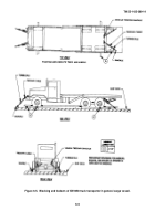
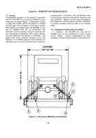
Figure 7-5 shows an isometric view of the truck
transporter, and figure 7-6 shows a rear view of the truck
transporter.
b.
When the vehicle is loaded and tied down, the
handbrakes must be set.
The transmission gearshift
must be in neutral.
c.
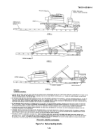
Fire Unit slinging and railcar loading details are
shown in figures 6-2 and 7-8, respectively.
Blocking
details for lading are presented in figure 7-9.
Table 7-2.
Application of Materials for Loading and
Securing XM1058 Truck Transporter (Figs 7-5
Through 7-6)
Item
No. Required
Application
A
8
Wheel blocks.
Place the 450 end of block
against a wheel.
Nail through heel of block
with three 40d and two 60d nails.
Toenail
each side to car floor with two 40d nails.
B
2
Rubbing strips, 2-inch x 6-inch x 7-foot 6-
inch.
Position on edge of wheel block, and
nail to lower piece marked C with one 12d
nail every 8 inches.
C
2
Side blocks, 2-inch x 4-inch x 7-foot 6-inch
(tripled).
Nail the first piece to the car floor
with one 30d nail every 8 inches.
Nail each
additional piece in a like manner.
D
2
Rubbing strips, 2- x- x 36-inch.
Position on
edge of side block, and nail to lower piece
marked E with five 12d nails.
E
2
Side blocks, 2- x 6- x 36-inch (tripled).
Nail
the first piece to the car floor with five 30d
nails.
Nail each additional piece in a like
manner.
7-6
Back to Top

