TM-9-2920-242-35 - Page 11 of 110
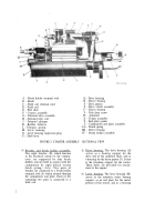
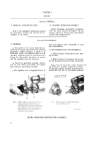
A - Brush holder terminal stud
B - Brush
C - Field coil terminal stud
D - Field coil
E - Pole shoe
F - Contact assembly
G - Solenoid relay assembly
H - Solenoid relay coil
Q - Drive housing
R - Sleeve bearing
S - Drive pinion
T - Drive clutch assembly
U - Sleeve bearing
V - Pole shoe screw
W - Armature
X - Frame assembly
J -
K -
L -
M -
N -
P
Solenoid plunger
Y - End plate gasket
Rubber bellows
Z - Commutator end plate assembly
Plunger spring
AA - Brush spring
Lever housing
BB - Sleeve bearing
Lever housing inspection plug
CC - Brush holder assembly
Shift lever
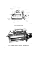
FIGURE 2. STARTER ASSEMBLY - SECTIONAL VIEW
(4)
Brushes and brush holder assembly.
(5)
The eight brushes
(B), which function
as the electrical contact to the commu-
tator, are supported by four brush
holders and are held in contact with the
commutator by eight helical torsion
brush springs (AA). Two pairs of
brushes are connected to a brush holder
terminal stud (A) which extends through
(6)
the commutator end plate. Each of the
remaining two pairs is connected to a
field coil.
Drive housing. The drive housing (Q)
serves as a bearing support for the
drive end of the armature shaft, and as
a housing for the drive pinion (S). It also
is the attaching support for the starter.
Three holes are provided for attach-
ment to the engine.
Lever housing. The lever housing (M)
serves as the armature center bearing
support, as an end plate for the motor
portion of the starter, and as a housing
2
Back to Top

