MWO-9-2320-272-20-7 - Page 5 of 14
MWO 9-2320-272-20-7
9.
SPECIAL TOOLS; TOOL KITS; JIGS; TEST, MEASUREMENT AND DIAGNOSTIC EQUIPMENT (TMDE);
AND FIXTURES REQUIRED.
a.
Hand tools necessary to apply MWO are contained in this tool kit:
NOMENCLATURE
NSN
CAGEC
SUPPLY CATALOGUE
Tool Kit, General Mechanic's
50980
SC 5180-90-CL-N26
b.
Metal drilling equipment necessary to apply MWO is contained in this shop set:
NOMENCLATURE
NSN
CAGEC
SUPPLY CATALOGUE
Shop Equipment, Machine Shop: 3470-00-754-0708
19204
SC 3470-95-CL-A02
Field Maintenance, Basic
10.
MODIFICATION PROCEDURES.
a.
Vehicle Preparation.
(1)
Remove battery ground cable.
(Refer to TM 9-2320-272-20.)
(2)
Drain air reservoirs.
(Refer to TM 9-2320-272-10.)
(3)
Remove front limiting valve.
(Refer to TM 9-2320-272-20.)
(4)
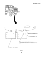
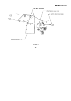
Using 12450248 template plate, locate, mark, and drill two 0.125-inch diameter pilot holes in
support bracket as shown in figure 1.
(5)
Enlarge two 0.125-inch diameter pilot holes drilled in step (4) to 0.344-inch diameter holes as
shown in figure 1.
b.
Front Brake Valve Installation.
NOTE
Ensure when applying pipe sealant that first two starter threads are
clear of pipe sealant.
(1)
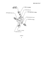
Remove nut, insert, and sleeve from 8-6 100202BA elbow.
Apply 592-31 pipe sealant to threads
on elbow and install into supply port of 11602155 front brake valve as shown in figure 2.
(2)
Apply pipe sealant to threads on 8-6 120202B elbow and install into exhaust port of front brake
valve as shown in figure 2.
(3)
Apply pipe sealant to threads on two 8-6 120102B adapters and install into left and right
delivery ports of front brake valve as shown in figure 2.
(4)
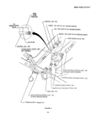
Secure front brake valve to support bracket with two B1821BH031F088N screws and
MS51943-34 nuts as shown in figure 3.
NOTE
The color of lines (for steps (6), (7), (8), and (9)) has been added as an
aid for installation purposes.
(5)
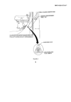
Connect two existing application lines (front service brake) to adapters (left and right delivery
ports) as shown in figure 4.
5
Back to Top

