MWO-9-2330-390-35-1 - Page 32 of 48
MWO 9-2330-390-35-1
B-2
APPENDIX B.
MANEUVERING POSITION (Con’t).
CAUTION
•
Proceed slowly and with caution to prevent equipment damage.
NOTE
•
If operating a dolly half equipped with side lift kit, extension of lift and positioning
cylinders should stop when top beam vertical tubes have extended approximately 49
in. (124 cm) and positioning cylinder limit lines are just visible.
(4)
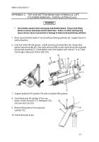
Pull down on two lift cylinder levers (56) to extend lift cylinders (73) and positioning
cylinders (2).
Stop when near (left side) top beam vertical tube (58) reaches within ½ in.
(13 mm) of hydraulic control valve (74) and fittings (90).
(5)
Continue to pull down on two lift cylinder levers (56), allowing near (left side) lift
cylinder (73) to lead far (right side) lift cylinder.
Maintain clearance of 1/8 in. (13 mm).
Back to Top

