TB-9-2320-279-13-1 - Page 60 of 524
TB 9-2320-279-13-1
0010-4
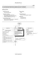
AC HEATER/EVAPORATOR BLOWER DOES NOT OPERATE - Continued
DRAFT
-
-
-
-
-
-
-
-
-
-
-
-
-
-
-
-
-
-
-
-
-
-
-
-
-
-
-
-
-
-
-
-
-
-
-
-
-
-
-
-
-
-
-
-
-
-
-
-
-
-
-
-
-
-
-
-
-
-
-
-
-
-
-
-
-
-
-
-
-
-
-
-
-
-
-
-
-
-
-
-
-
-
-
-
-
-
-
-
-
-
-
-
-
-
-
-
-
-
-
-
-
-
-
-
-
-
-
-
-
-
-
-
-
-
-
-
-
-
-
-
-
-
-
-
-
-
-
-
-
-
-
-
-
-
-
-
-
-
-
-
-
-
-
-
-
-
-
-
-
-
-
-
-
-
-
-
-
-
-
-
-
-
-
-
-
-
-
-
-
-
-
-
-
-
-
-
-
-
-
-
-
-
-
-
-
-
-
-
-
-
-
-
-
-
-
-
-
-
-
-
-
-
-
-
-
-
-
-
-
-
-
-
-
-
-
-
-
-
-
-
-
-
-
-
-
-
-
-
-
-
-
-
-
-
-
-
-
-
-
-
-
-
-
-
-
-
-
-
-
-
-
-
-
-
-
-
-
-
-
-
-
-
-
-
-
-
-
-
-
-
-
-
-
-
-
-
-
-
-
-
-
-
-
-
-
-
-
-
-
-
-
-
-
-
-
-
-
-
-
-
-
-
-
-
-
-
-
-
-
-
-
-
-
-
-
-
-
-
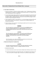
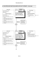
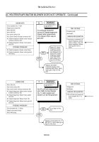
KNOWN INFO
Circuit breaker No. 11 OK.
Engine start switch OK.
Wire 1640 OK.
POSSIBLE PROBLEMS
Wire 1082 faulty.
Fan control switch faulty.
Fan control switch harness connector loose
or faulty.
AC heater/evaporator blower motor resistor
harness connector loose or faulty.
AC heater/evaporator blower motor power
wire faulty.
AC heater/evaporator blower motor faulty.
AC heater/evaporator blower motor ground
wire faulty.
2.
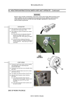
Are 22 to 28 vdc measured on
wire 1082 at fan control
switch, when engine start
switch is in the ON position?
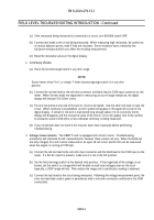
Repair wire 1082
(see Appendix A) or
notify Supervisor.
Verify repair, go to
Step 9 of this fault.
NO
YES
Read WARNING on
page 0010-5.
WARNING
-
-
-
-
-
-
-
-
-
-
-
-
-
-
-
-
-
-
-
-
-
-
-
-
-
-
-
-
-
-
-
-
-
-
-
-
-
-
TEST OPTIONS
Voltage test.
Multimeter.
REASON FOR QUESTION
If 22 to 28 vdc are not
measured, wire 1082 is
faulty.
-
-
-
-
-
-
-
-
-
-
-
-
-
-
-
-
-
-
-
-
-
-
-
-
-
-
-
-
-
-
-
-
-
-
-
-
-
-
-
-
-
-
-
-
-
-
-
-
-
-
-
-
-
-
-
-
-
-
-
-
-
-
-
-
-
-
-
-
-
-
-
-
-
-
-
-
-
-
-
-
-
-
-
-
-
-
-
-
-
-
-
-
-
-
-
-
-
-
-
-
-
-
-
-
-
-
-
-
-
-
-
-
-
-
-
-
-
-
-
-
-
-
-
-
-
-
-
-
-
-
-
-
-
-
-
-
-
-
-
-
-
-
-
-
-
-
-
-
-
-
-
-
-
-
-
-
-
-
-
-
-
-
-
-
-
-
-
-
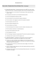
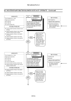
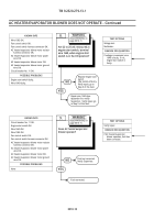
KNOWN INFO
Circuit breaker No. 11 OK.
Engine start switch OK.
Wire 1640 OK.
Wire 1082 OK.
POSSIBLE PROBLEMS
Fan control switch faulty.
Fan control switch harness connector loose
or faulty.
AC heater/evaporator blower motor resistor
harness connector loose or faulty.
AC heater/evaporator blower motor power
wire faulty.
AC heater/evaporator blower motor faulty.
AC heater/evaporator blower motor ground
wire faulty.
3.
Is continuity measured
across fan control switch
from terminal wire 1082 to
terminal orange wire, when
switch is in high speed (fully
clockwise) position?
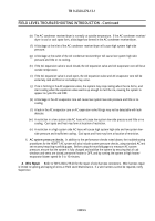
Replace fan control
switch (WP 0031).
Verify repair, go to
Step 9 of this fault.
NO
YES
Read WARNING on
page 0010-5.
WARNING
TEST OPTIONS
Continuity test.
Multimeter.
REASON FOR QUESTION
If continuity is not measured,
fan control switch is faulty.
Back to Top

