TB-9-2320-279-13-P-2 - Page 448 of 460
II
111450-1
Rev. A
Page 6
3.
C4ISR MOUNTING HARDWARE KIT ASSEMBLY PROCEDURES
WARNING
THE EDGES OF THE METAL ARMOR PANELS MAY BE SHARP.
PROTECTIVE GLOVES SHOULD BE WORN BY THE INSTALLATION TEAM
TO PREVENT PERSONAL INJURY.
3.1
INSTALL MTS BRACKET PLATE ASSEMBLY, P/N 111449-1
Install the MTS Bracket Plate Assembly, P/N 111449-1, onto the two through-panel studs on the
Armor Panel using one Washer, 0.250-in. ID, and one Locknut, 0.250 – 20, on each of the
through-panel studs (See Figure 2.2).
3.2
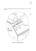
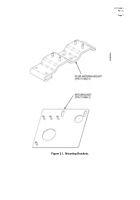
INSTALL PLGR ANTENNAE MOUNTING BRACKET, P/N 111452
Install the PLGR Antennae Mounting Bracket by clamping it onto the Roof Armor Panel (See
Figure 2.3).
The clamp is secured to the Roof Armor Panel using two Bolts, 0.250 x 28 – 1.000,
and two Jam Nuts, 0.250 – 28.
Torque to 6 ft-lb each.
Redundant fastening may be achieved
by using the two center studs that are welded to the roof; however, it is not essential that these
studs be used.
The two center studs protruding through the Bracket are secured with one
Washer, No. 10, and one Locknut, 10 - 24, each.
3.3
MOUNTING THE PLGR ANTENNAE
The PLGR Antennae are secured to the Mounting Bracket stud (See Figure 2.3) using two
Washers, No. 10, and two Locknuts, 10 – 24, for each antenna.
3.4
SECURING THE “P” CLAMPS FOR THE ANTENNA WIRES
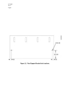
Two holes must be drilled in the Roof Support Bracket (See Figure 3.2) if the Bracket is not
received pre-drilled.
A 9/23-in. drill bit is used to drill the two holes with the Support Bracket in
place.
The “P” Clamps can then be attached to the Roof Support Bracket as indicated in
Figure 2.1 and 2.2 using the existing hardware.
Back to Top


