TB-9-2320-279-13-P-4 - Page 226 of 744
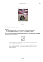
1
2
4
3
1516
1516A
1675
1435
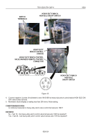
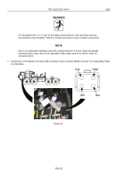
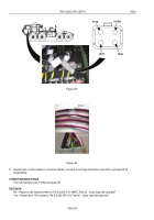
Figure 27.
2. Remove high idle active relay R10 (refer to TM 9-2320-315-14&P).
3. Start engine (refer to TM 9-2320-279-10).
4. Set PTO ENGAGE switch to ON position. (WP 0015)
5. Set heavy-duty winch control station HIGH IDLE ON/OFF switch to ON position. (WP 0015)
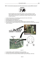
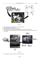
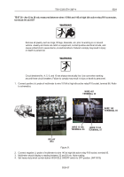
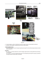
6. Connect positive (+) probe of multimeter to wire 1516A at high idle active relay R10 socket, terminal 86. Refer
to schematics.
RELA
Y
R10
WIRE 1516A
TERMINAL 86
WIRE 151-D
TERMINAL 87
WIRE 451
TERMINAL 30
WIRE 145
TERMINAL 85
Figure 28.
7. Connect negative (-) probe of multimeter to a known good ground.
TB 9-2320-279-13&P-4
0024
0024-34
Back to Top

