TB-9-2320-279-13-P-4 - Page 91 of 744
6
5
8
7
2
3
4
4
9
10
1
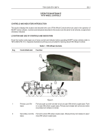
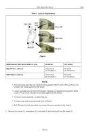
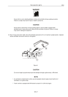
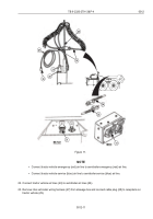
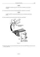
Figure 2.
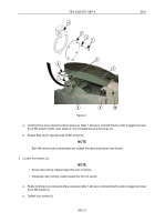
a. Install lockring (4) so desired surface area (see Table 1 above) is oriented directly under engagement area
(6) of fifth wheel (5) with cover plate (3), four lockwashers (2) and screws (1).
b. Repeat Step (2) for opposite side of fifth wheel (5).
NOTE
Both fifth wheel lockout assemblies are rotated the same way (driver side shown).
3. Loosen four screws (1):
NOTE
•
Driver side lockring rotates toward the rear of vehicle.
•
Passenger side lockring rotates toward the front of vehicle.
a. Rotate lockring (4) so desired surface area (see table 1 above) is oriented directly under engagement area
(6) of fifth wheel (5).
b. Tighten four screws (1).
TB 9-2320-279-13&P-4
0012
0012-3
Back to Top


