TB-9-2320-302-13-P-1 - Page 223 of 380
Installation Manual – P/N 0257550622-00
(Doc No.:
II
113500-1 D)
Freightliner M915 / M916 -
Crew Protection Kit
Page 31 of 125
5.3.2
Installation Instructions:
1.
Arrange parts and fasteners at the installation location.
2.
Prepare a lifting device cable of lifting approximately 110 kg (242 lb).
3.
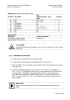
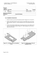
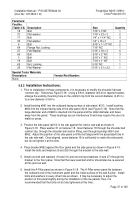
Place part #659 on the front bumper.
Align item #971 with the front bumper outboard edge.
4.
Connect part #659 with part #971 using six (6) 5/8" x 2-1/2" bolts (#383), 5/8" Star-Washers,
5/8" x 1-1/4" x 1/8" Flat-Washers, and 5/8" Nuts.
Fasteners are arranged in the following
order: Bolt, Star-Washer, Flat-Washer, and Nut.
Install all 6 bolts and associated nuts and
washers.
Tighten the top 3 bolts first, and then tighten the lower 3 bolts.
Torque to 230 Nm
(170 ft-lb).
Note: Thread-locking compound must be used on these fasteners.
5.
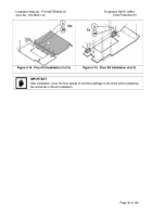
Lift item #007 into position as shown in Figure 5-9.
Insert the aft-most bolts first (item 22).
Temporarily use the aft fasteners to hold the deflector in position.
Install the center and
forward fasteners next (do not tighten the bolts until all fasteners are in place).
Apply
thread-locking compound to the bolts. Install fasteners in the following order:
•
Star-Washer
•
Flat-Washer
•
Insert bolt from beneath
•
Nut.
6.
Tighten bolts to a 122 N-m (90 ft-lb) torque.
7.
Ensure that the flexible brake lines are not rubbing on the inside lower edge of the Wheel
Zone Deflector (#007).
If the lines are rubbing near the Wheel Zone Deflector, relocate
them by loosening the hose end fitting, twisting the lines and then re-tightening the hose end
fittings
Back to Top


