TB-9-2320-302-13-P-1 - Page 257 of 380
Installation Manual – P/N 0257550622-00
(Doc No.:
II
113500-1 D)
Freightliner M915 / M916 -
Crew Protection Kit
Page 65 of 125
4.
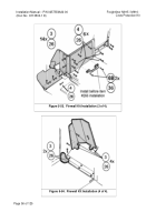
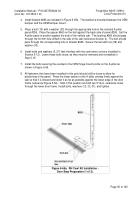
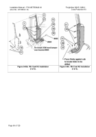
Install bracket #965 as indicated in Figure 5-65b.
The bracket is mounted between the OEM
bumper and the OEM bumper mount.
5.
Place a bolt (13) with a washer (30) through the appropriate hole in the external A-pillar
panel #256.
Place the spacer #960 on the bolt against the back side of panel #255.
Set the
A-pillar panel in position against the side of the vehicle cab.
The bushing #960 should pass
through the 30-mm hole drilled in the side of the cab (reference Section 2).
The bolt should
pass through the corresponding hole in bracket #965.
Secure the bolt with nut (38) and
washer (30).
6.
Install bolts and washers (2, 27) that interface with the cowl armor corners (installed in
Section 5-12).
Leave these bolts loose, as they must be removed and reinstalled in
Step 5.15.
7.
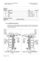
Install the bolts securing the overlap to the OEM hinge mount points on the A-pillar as
shown in Figure 5-66.
8.
All fasteners that have been installed to this point should still be loose to allow for
positioning of the panel.
Press the lower section of the A-pillar overlap firmly against the
cab so that it is inboard and down it as far as possible against the lower edge of the door
frame (reference Figure 5-66).
Hold in this position and drill two 5/16-in. clearance holes
through the lower door frame. Install bolts, washers (12, 33, 37), and tighten.
Figure 5-65a.
RH Cowl Kit Installation -
Door Step Preparation (1 of 3).
Back to Top


