TB-9-2320-335-13-P - Page 71 of 680
TB 9-2320-335-13&P
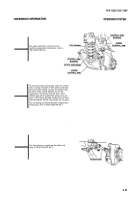
1. With engine off, disconnect pressure hose
from hydro-boost and connect tube and
quick-disconnect to hydro-boost.
NOTE
Have drainage container ready to catch
fluid.
2. Connect adapter and quick-disconnect to
pressure hose.
3. Connect hose from valve on power steering
analyzer to tube and quick-disconnect on
hydro-boost.
4. Connect hose from gauge side of
power steering analyzer to adapter and
quick-disconnect on pressure hose.
5. Connect STE/ICE-R to vehicle diagnostic
connector and set for measuring RPM
(refer to TM 9-2320-387-24-1).
6. Open analyzer valve to full open position.
7. Start engine (refer to TM 9-2320-387-10).
8. Remove power steering reservoir cap and
turn steering wheel all the way left, hold in
place for 3 seconds, then repeat process with
steering wheel all the way right. This
releases air from the system.
9. Return steering wheel to center position and shut engine off (refer to TM 9-2320-387-24-1).
10. Check and add power steering fluid to reach FULL COLD level in reservoir
(refer to TM 9-2320-387-10).
11. Start engine (Refer to TM 9-2320-387-10) and allow engine to idle and reach operating temperature of
190° F to 230° F.
12. Check for proper engine idle speeds and adjust if necessary (refer to TM 9-2320-387-24-1).
6.5L engine
700±25 RPM
13. Ensure analyzer valve is in full open position and engine is at proper idle speed.
14. Initial pressure should be 250–400 psi and a flow of 4.00 gpm. If these specifications aren't present,
check installation of analyzer and check power steering system (Refer to TM 9-2320-387-10).
15. With power steering system working properly, partially close analyzer valve until pressure reaches
700 psi. If flow rate varies more than 1 gpm from the initial reading, replace power steering pump
(TM 9-2320-387-24-1).
CAUTION
Do not leave analyzer valve fully closed for more than 3 seconds. Severe damage may
occur to power steering pump.
16. With engine at idle, close and open analyzer valve three times, recording pressure each time.
All readings should be 1600 psi or higher, if pressure is lower, replace power steering pump
(TM 9-2320-387-24-1).
17. With analyzer valve in the open position, increase engine rpm to 1500 and record fluid flow. If fluid flow
varies more than 1 gpm from initial reading, replace power steering pump (TM 9-2320-387-24-1).
2-49
Check hydraulic hoses, power steering pump, power steering cooler, hydro-booster unit, and steering gear.
See hose replacement procedures (refer to para. 8-24.2). Check power steering cooler for bent fins or any
other airflow restrictions. Straighten fins or replace power steering cooler (refer to para. 3-8.1) if damaged
beyond repair.
HOSE
(GAUGE SIDE)
HOSE
(VALVE
SIDE)
GAUGE
POWER
STEERING
ANALYZER
ADAPTER/QUICK-
DISCONNECT
PRESSURE HOSE
TUBE/QUICK-
DISCONNECT
HYDRO-
BOOST
VALVE
REFERENCE INFORMATION
STEERING SYSTEM
Back to Top


