TB-9-2350-368-25 - Page 101 of 120
TM 9-2350-368-25
5-3
NOTE
•
All checks should be made with suitable multimeter and
powerplant test stand master switch in the on position.
•
Battery voltage can range from 22 to 26 volts without the engine
running.
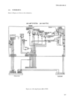
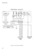
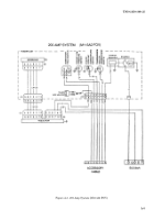
5-3.
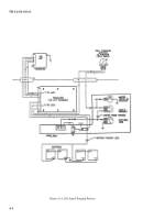
A3 WIRING HARNESS
1. Turn master switch on. Check four wire
regulator harness
at the end that connects to the regulator.
You should get the following readings:
Pin A
Not used
Pin B
Circuit number 1
Battery voltage
Pin C
Circuit number 2
Battery voltage
Pin D Circuit number 2A
Battery voltage
Pin E
Circuit number 1A
0 volts
Pin F
Not used
Pin G Not used
2. Turn master switch on. Check three wire
regulator harness
at the end that connects to the regulator.
You should get the following readings:
Pin A
Circuit number 2A
Battery voltage
Pin B
Not used
Pin C
Circuit number 2
Battery voltage
Pin D Not used
Pin E
Not used
Pin F
Circuit number 1B
0 volts
3. Turn master switch on. Check
accessory harness
at the end. You should get the following readings:
Pin A
Not used
Pin B
Circuit number 1B
0 volts
Pin C
Circuit number 406
Battery voltage (with air box heater switch on.)
Pin D Circuit number 34
Battery voltage
Pin E
Circuit number 33
14 volts
Pin F
Circuit number 1C
Battery voltage
Pin G Circuit number 327
Battery voltage
Pin H Circuit number 74
Battery voltage
Pin J
Not used
Pin K Circuit Number 406A 0 volts
Pin L
Not used
Pin M Not used
Pin N Not used
Pin O Not used
4. Turn master switch on. Check
starter harness
at the end. You should get the following readings:
Pin A
Not used
Pin B
Circuit number 6A
Battery voltage
Pin C
Not used
Pin D Not used
Pin E
Circuit number 6
Battery voltage
Back to Top


