TB-9-3950-253-13-P
PALLETIZED LOAD SYSTEM TRUCK, M1075 and M1075A1 (PLS) AND HEAVY EXPANDED MOBILITY TACTICAL TRUCK, M1120, M1120A2, AND M1120A4 (HEMTT), ENHANCED CONTAINER HANDLING UNIT (E-CHU)
TECHNICAL BULLETIN; OPERATOR AND FIELD MAINTENANCE, INSTALLATION INSTRUCTIONS, AND REPAIR PARTS AND SPECIAL TOOLS LIST
JULY 2009
TB-9-3950-253-13-P - Page 210 of 704
TB 9-3950-253-13&P
Change 1
0019-30
0019
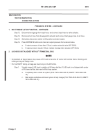
HYDRAULIC SYSTEM - CONTINUED
NO RETRIEVE OR STOW FUNCTION – CONTINUED.
Step 16.
With engine on, press unstow button on Control Panel and check for hydraulic pressure.
a.
If hydraulic pressure is <100 psi (689 kPa) turn off engine and replace cylinder (WP 0023).
b.
If hydraulic pressure is >100 psi (689 kPa), turn off engine, remove pressure gauge from T-
fitting, T-fitting from hose and cylinder, install relief hose on cylinder and proceed to next
step.
Step 17.
Remove relief hose from lower fitting on output side of manifold, install T-fitting between hose
and cylinder and connect pressure gauge to T-fitting.
Step 18.
With engine on, press unstow button on Control Panel and check for hydraulic pressure.
a.
If hydraulic pressure is <100 psi (689 kPa) turn off engine and replace relief hose from cyl-
inder to manifold (WP 0044).
b.
If hydraulic pressure is >100 psi (689 kPa), turn off engine, remove pressure gauge from T-
fitting, T-fitting from hose and manifold, install relief hose on manifold and proceed to next
step.
Step 19.
Remove relief hose from lower fitting on input side of manifold, install T-fitting between hose and
cylinder and connect pressure gauge to T-fitting.
Step 20.
With engine on, press unstow button on Control Panel and check for hydraulic pressure.
a.
If hydraulic pressure is >100 psi (689 kPa) turn off engine and replace manifold (WP 0026).
b.
If hydraulic pressure is <100 psi (689 kPa), turn off engine, remove T-fitting from hose and
manifold, and replace relief hose from manifold to quick-disconnect fitting (WP 0044).
PNEUMATIC SYSTEM
NOTE
•
Tag all wires, connections, hoses, and fittings upon removal.
•
Install all wires, connections, hoses, and fittings as tagged during removal.
1. NO STOWAGE LATCH FUNCTION.
Step 1.
Check pneumatic hose from air tank to valve and from valve to actuator for damage and loose
or damaged fittings (WP 0044).
Replace damaged hose or fittings (WP 0044).
Step 2.
Check stowage latch capture plate for damage and loose or damaged hardware (WP 0022).
Replace damaged capture plate or hardware (WP 0022).
Step 3.
Check stowage latch actuator for damage and loose or damaged hardware (WP 0022).
Replace damaged actuator or hardware (WP 0022).
MALFUNCTION
TEST OR INSPECTION
CORRECTIVE ACTION
0.
Back to Top

