TM-5-2350-262-20-1 - Page 336 of 776
TM 5-2350-262-20-1
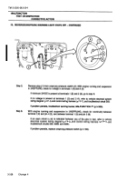
Step 6.
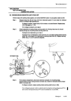
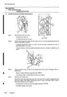
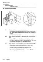
With engine running and suspension in UNSPRUNG, check for continuity between pins
(12) and (13); and between pins (11) and (14).
If an open circuit
is indicated between any of the pins in test, refer to vehicle
electrical system wiring diagram (p FP-3) and control wiring harness (p FP-7), and
troubleshoot circuits 509, 509B, and 509C.
If problem persists, replace unsprung pressure switch (p 4-139).
MALFUNCTION
TEST OR INSPECTION
CORRECTIVE ACTION
75.
WARNING BUZZER AND EMERGENCY FLASHER DO NOT OPERATE WHEN SUSPENSION
IS IN UNSPRUNG AND TRANSMISSION IS IN REVERSE - CONTINUED
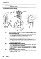
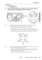
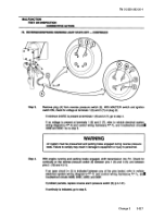
Step 5.
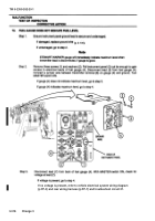
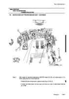
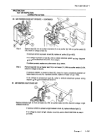
Remove plug (9) from unsprung pressure switch (10).
With engine running and
suspension in UNSPRUNG, check for voltage at pins (11) and (12).
If minimum 24 VDC is present at pins (11) and (12), go to step 6.
If no voltage is present at pins (11) and (12), refer to vehicle electrical system wiring
diagram (p FP-3) and control wiring harness (p FP-7), and troubleshoot circuit 509.
If problem persists, troubleshoot warning buzzer, MALFUNCTION 77 (p 3-329).
11
13
9
14
12
Change 4
3-325 (325.1 through 325.8 deleted)
Back to Top

