TM-5-2350-262-20-1 - Page 453 of 776
TM 5-2350-262-20-1
4-102 (4-103 and 4-104 deleted)
Change 3
Note
•
Tag electrical leads prior to removal for
installation.
•
Remove sleeve nuts only if damaged.
A
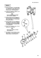
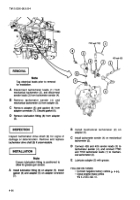
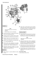
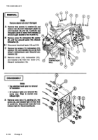
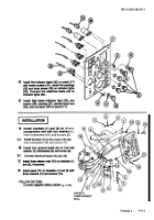
Remove three screws (1), washers (2), and sleeve
nuts (3) from instrument panel (4).
B
Carefully pull driver’s instrument panel (4) away
from brackets (5) to expose the rear of panel (4).
C
Remove screw (6), and electrical lead (7),
ventilation fan wiring harness, from fan switch (8).
D
Remove nut (9), lockwasher (10), from fan motor
(11).
Discard lockwasher (10).
E
Remove screw (12), lockwasher (13), washer
(14), nut (15),
and ground lead (16), from driver’s
compartment wall.
Discard lockwasher (13).
F
Disconnect electrical connector (17) from
ventilation fan wire receptacle (18), and remove
ventilation fan wiring harness (7).
REPAIR
A
Refer to page 3-1 to repair ventilation fan wiring
harness.
INSTALLATION
A
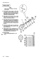
Install ventilation fan wiring harness (7), electrical
connector (17) to vent fan wire receptacle (18).
Route harness (7) to back of instrument panel (4).
Note
Align tangs on connector for correct
installation.
B
Install ground lead (16) to driver’s compartment
wall with nut (15), washer (14), new lockwasher
(13) and screw (12).
Install other end of ground
lead with new lockwasher (10) and nut (9).
C
Install other end of vent fan wiring harness (7) to
fan switch (8) with screw (6).
Ensure three wires
are connected to the fan switch with screw (6).
D
Carefully replace driver’s instrument panel (4) on
brackets (5) with three washers (2), nuts (3), and
screws (1).
FOLLOW-ON TASK:
Connect battery cable (p 4-84)
15
17
12
13
18
14
7
3
4
7
11
5
2
1
8
6
16
9
10
5
B
Clean ends of ground lead (16) and mounting
surface with emery cloth until metal is clean and
free of paint or corrosion.
This will ensure a good
ground is obtained during re-assembly.
REMOVAL
Back to Top

