TM-5-2350-262-20-3 - Page 265 of 319
2
5
3
4
2
9
8
9
6
7
1
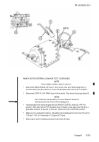
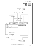
Track adjustment is provided by hydraulic pressure from the compensating pump and controlled by
electric current tapped at the UNSPRUNG switch.
In the SPRUNG or UNSPRUNG mode, hydraulic pressure is
delivered to the track adjuster manifold from line nine (9) and returned through line seven (7) at the left manifold.
WARNING
High pressure is present in the M9 hydraulic system.
Do not disconnect any hydraulic
system component unless hydraulic system pressure has been relieved.
Ensure each
hydraulic control lever is moved several times through all positions and hydraulic tank
dipstick is slowly loosened to relieve pressure.
Failure to comply may result in severe
injury or death to personnel.
NOTE
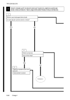
Use these procedures to troubleshoot either left or right track adjuster cylinder.
The
hydraulic valves are equipped with manual operators which can be used to check the
hydraulic portion of the system.
If everything functions by the manual hydraulic
operators, the problem will be in the electric circuit (refer to TM 5-2350-262-20-1).
HIGH-PRESSURE
CIRCUIT
RETURN
SUPPLY
COMPONENTS:
1.
COMPENSATING PUMP
2.
HIGH-PRESSURE FILTER
3.
MAIN ACCUMULATOR
4.
RETURN LINE FILTER
5.
DIRECTIONAL CONTROL
VALVE BANK
6.
HYDRAULIC RESERVOIR
7.
MANIFOLD, LEFT HAND
8.
TRACK ADJUSTING MANIFOLD
ASSEMBLY
9.
TRACK ADJUSTING CYLINDERS
18
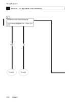
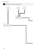
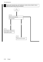
TRACK (LEFT OR RIGHT) WILL NOT TIGHTEN OR LOOSEN, SEMI-AUTOMATIC
TRACK
ADJUSTER (NEW PRODUCTION)
3-232
Change 1
TM 5-2350-262-20-3
Back to Top


