TM-5-2350-262-34 - Page 500 of 516
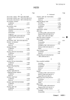
TM 5-2350-262-34
Repair.
............................................................
4-6
Brackets, electrical:
Installation .
.....................................................
4-51
Removal .
........................................................
4-50
Bump stop cylinder, front:
Assembly.
.......................................................
4-322
Cleaning .
........................................................
4-322
Disassemby.
...................................................
4-321
Inspection .
......................................................
4-322
Installation (TM 5-2350-262-20-2)
Removal (TM 5-2350-262-20-2)
Repair.
............................................................
4-322
Deleted
C
Charging pump and housing, transmission:
Inspection .
......................................................
4-196
Installation .
.....................................................
4-197
Removal .
........................................................
4-196
Charging pump housing, transmission:
Assembly.
.......................................................
4-200
Cleanng .
.........................................................
4-200
Disassembly .
..................................................
4-199
Inspection .
......................................................
4-200
Repair .
............................................................
4-200
Cleaning, general .
...............................................
2-9
Clutch cover and gasket, transmission:
Installation .
.....................................................
4-204
Removal .
........................................................
4-203
Common tools and equipment.
...........................
2-7
Deleted
Control valve, hydraulic shift:
Assembly .
.......................................................
4-182
Cleaning .
........................................................
4-181
Disassembly .
..................................................
4-180
Inspection .
......................................................
4-181
Installation (TM 5-2350-262-20-2)
Removal (TM 5-2350-262-20-2)
Control wiring harness:
Installation .
.....................................................
4-41
Removal .
........................................................
4-30
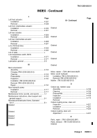
INDEX - Continued
Page
Page
B - Continued
C - Continued
Repair.
............................................................
4-38
Cylinder, apron hydraulic:
Assembly .
....................................................
4-93
Disassembly .
...............................................
4-90
Inspection .
...................................................
4-92
Installation (TM 5-2350-262020-1)
Removal (TM 5-2350-262-20-1)
Repair .
.........................................................
4-92
Cylinder, ejector hydraulic:
Assembly.
....................................................
4-98
Disassembly.
...............................................
4-96
Inspection .
...................................................
4-98
Installation (TM 5-2350-262-20-1)
Removal (TM 5-2350-262-20-1)
Repair .
.........................................................
4-98
Cylinder, front bump stop:
Assembly.
....................................................
4-322
Cleaning .
.....................................................
4-322
Disassembly.
...............................................
4-321
Inspection .
...................................................
4-322
Installation (TM 5-2350-262-20-2)
Removal (TM 5-2350-262-20-2)
Repair .
.........................................................
4-322
Cylinder, track adjusting:
Assembly.
....................................................
4-317
Disassemby.
................................................
4-314
Inspection .
...................................................
4-316
Installation (TM 5-2350-262-20-2)
Removal (TM 5-2350-20-262-2)
Repair .
.........................................................
4-316
D
Destruction of Army materiel
to prevent enemy use .
...................................
1-1
Diagrams, schematic .
......................................
D-1
Directional control valve bank:
Assembly.
....................................................
4-119
Cleaning .
.....................................................
4-119
Disassembly.
...............................................
4-118.1
Installation (TM 5-2350-262-20-2)
Removal (TM 5-2350-262-20-2)
Repair .
.........................................................
4-119
Direct support and general support
integrated maintenance instructions.
.............
2-1
Discharger, wiring harness:
(TM 5-2350-262-20-1)
Deleted
INDEX 2
Change 3
Back to Top


