TM-5-2350-378-23-P - Page 482 of 644
INSTALLATION - Continued
6.
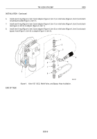
Install new O-ring (Figure 4, Item 2) and adapter (Figure 4, Item 1) on relief valve (Figure 4, Item 3) and attach
to bulkhead bracket (Figure 4, Item 7).
7.
Install new O-ring (Figure 4, Item 2) and adapter (Figure 4, Item 1) on relief valve (Figure 4, Item 3) and attach
tee (Figure 4, Item 6) to adapter (Figure 4, Item 1).
8.
Install new O-ring (Figure 4, Item 2) and adapter (Figure 4, Item 5) on relief valve (Figure 4, Item 3) and attach
bypass hose (Figure 4, Item 4) to adapter (Figure 4, Item 5).
7
6
1
2
2
5
4
3
2
1
M0047HDC
Figure 4.
Valve V21 (V22), Relief Valve, and Bypass Hose Installation.
END OF TASK
TM 5-2350-378-23&P
0039
0039-8
Back to Top


