TM-5-3805-254-14-P-1 - Page 24 of 590
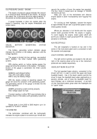
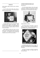
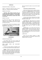
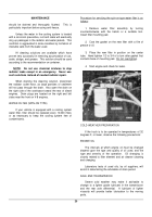
OIL CHECK PROCEDURE
Before checking the oil level, clean
around the end of the fill pipe before
removing the dipstick.
Dirt or foreign
matter must not be permitted to enter
the oil system because it can cause
valves to stick, cause undue wear of
transmission parts or clog passages.
Check the oil level by the following
procedure:
1.
Operate the transmission in a
drive
range
until
normal
operating temperature (160-
220
°
F) is reached.
2.
Shift through all drive ranges
to fill the clutches and oil
passages.
3.
Park the vehicle on a level
spot, shift to neutral (N) and
apply the parking brake.
Let
the engine run at idle speed.
4.
Check the oil level after
wiping the dipstick clean.
The safe operating level is
between the FULL and ADD
marks on the dipstick.
5.
If not within this range, add or
drain oil as necessary to
bring the level to the FULL
mark.
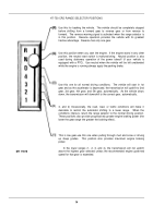
HOW
TO
KEEP
LITTLE
PROBLEMS
FROM
BECOMING
BIG PROBLEMS
By observing the operation of the
transmission and making a few
periodic checks, minor mechanical
problems can be kept from becoming
major overhaul.
If one of these conditions occur-
•
Shifting feels odd.
•
Transmission automatically up-
shifts or downshifts at irregular
intervals.
Notify your vehicle maintenance
personnel.
MT17877
MAINTENANCE
2.
Separate screen retainer and magnet.
On some
units magnet and screen are one integral unit.
Magnet
action in filter screen will remove any metal particles that
may enter fuel system.
3.
Clean screen and magnet in cleaning solvent
and dry with compressed air.
4.
Reassemble magnet in screen.
Install filter
screen assembly in fuel pump with hole down.
5.
Replace spring on top of filter screen assembly.
6.
Replace cap; tighten to 20/25 foot pounds.
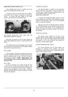
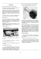
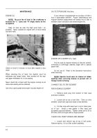
FAN BELT ADJUSTMENT
Always sho-ten distance between pulley centers so
the belt can be installed without force.
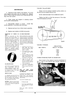
NOTE: REPLACE BELTS IN COMPLETE SETS
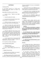
Tighten fan belts so that the pressure of the index
finger will depress as shown.
FAN BELT TENSION
DEFLECTION
BELT WIDTH
PER FT.
OF SPAN
1/2"
13/32"
11/16"
13/32"
3/4"
7/16"
7/8"
1/2"
1"
9/16"
POWER STEERING PUMP OIL RESERVOIR
The oil level in the reservoir must be maintained to
the "F" mark on the dipstick type indicator attached to
the filler cap.
Back to Top

