TM-5-3805-254-14-P-2 - Page 433 of 894
TRUCK SERVICE MANUAL
ENGINE
New
New
Worn
Part or Location
Minimum
Maximum
Limit
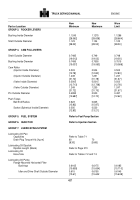
GROUP 9.
DRIVE UNITS
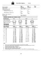
Fuel Pump and Compressor Drive
Bushing Inside Diameter
1.312
1.315
1.321
[33.32]
[33.40]
[33.55]
Drive Shaft Outside Diameter
1.3115
1.312
1.310
[33.312]
[33.32]
[33.27]
End Clearance
0.005
0.010
[0.13]
[0.25]
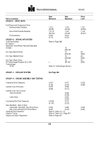
GROUP 10.
INTAKE AIR SYSTEM
Cold Starting Aids
Refer to Page 388
Air Cleaner
Restriction (Inch/Water) Naturally Aspirated
Oil Bath
15
[381.001
Dry Type (Normal Duty)
10
20
[254.00]
[508]
Dry Type (Medium Duty)
12
20
[304.80]
[508]
Dry Type (Heavy Duty)
15
20
All Turbocharged Engines 25 in.H20
[
381.00]
[508]
Turbocharger
VT-50
Refer To Turbocharger Section
GROUP 11.
EXHAUST SYSTEM
See Page 390
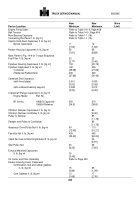
GROUP 14.
ENGINE ASSEMBLY AND TESTING
Crankshaft End Clearance
0.007
0.017
0.022
[0.18]
[0.43]
[0.56]
Cylinder Liner Protrusion
0.003
0.006
[0.08]
[0.15]
Cylinder Liner Out-of-round
Top/inch [25.40]
0.003
[0.08]
Lower Area
0.002
[0.05]
Connecting Rod Side Clearance
0.0045
0.013
[0.114]
[0.33]
Gear Backlash - Gear to Gear
Crankshaft, Camshaft, Fuel Pump Drive,
0.002
0.009
0.020
Idler, and Lubricating Oil Pump Gears
[0.05]
[0.23]
[0.50]
Camshaft End Clearance
Refer to Table 14-1 (7).
Injection Timing
Refer to Table 14-3, Page 397
Injector and Valve Adjustment
Refer to Page 407
429
Back to Top

