TM-5-3805-254-20-2 - Page 146 of 971
TM 5-3805-254-20-2
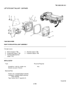
FRONT TURN SIGNAL
This task covers:
a.
Removal (page 2-795)
d.
Assembly (page 2-797)
b.
Disassembly (page 2-796)
e.
Installation (page 2-799)
c.
Inspection/Replacement
(page 2-796)
INITIAL SETUP
Tools
Materials/Parts - Continued
Screwdriver, cross-tip, number one
Lockwasher, mounting (four required)
Wrench, box-end, 1/2-inch (two
Pad, mounting
required)
Personnel Required
Materials/Parts
One
Gasket, lens (two required)
Gasket, marker lens
ACTION
LOCATION
ITEM
REMARKS
REMOVAL
NOTE
Steps given are typical for both left and right front turn signals.
1.
Front fender (1)
Four nuts (2), four
a.
Using two 1/2-inch open-end
lockwashers (3), four
wrenches, unscrew and take off.
flat washers (4),
b.
Get rid of lockwashers.
two screws (5), and
clamp (6)
TA244201
2-795
Back to Top


