TM-5-3805-264-13-P - Page 198 of 660
REMOVAL
NOTE
Wires should be tagged before disconnecting (WP 0072).
1.
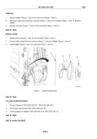
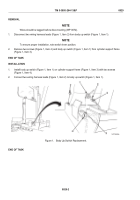
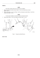
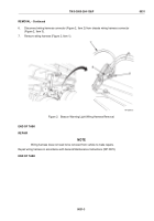
Disconnect two wiring harness leads (Figure 1, Item 2) from body up switch (Figure 1, Item 1).
NOTE
To ensure proper installation, note switch lever position.
2.
Remove two screws (Figure 1, Item 4) and body up switch (Figure 1, Item 1) from cylinder support frame
(Figure 1, Item 3).
END OF TASK
INSTALLATION
1.
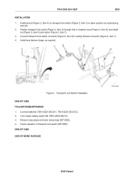
Install body up switch (Figure 1, Item 1) on cylinder support frame (Figure 1, Item 3) with two screws
(Figure 1, Item 4).
2.
Connect two wiring harness leads (Figure 1, Item 2) to body up switch (Figure 1, Item 1).
Figure 1.
Body Up Switch Replacement.
END OF TASK
TM 5-3805-264-13&P
0029
0029-2
Back to Top

