TM-5-3805-264-13-P - Page 474 of 660
TORQUE TABLES - Continued
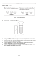
Figure 2.
Capscrew Head Markings.
2.
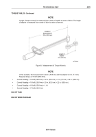
Count the number of threads per inch (Figure 3).
Figure 3.
Measuring Screw.
3.
Under the heading SIZE, look down the left hand column until you find the diameter of the screw you are
installing. (There will usually be two lines beginning with the same size.)
4.
In the second column under SIZE, find the number of threads per inch that matches the number of threads
you counted in Step 2. (Not required for metric screws.)
5.
To find the grade screw you are installing, match the markings on the head to the correct picture of
Capscrew Head Markings in the illustration preceding the torque tables.
6.
Look down the column under the picture you found in Step 5, until you find the torque limit (lb-in., lb-ft, or
N•m) for the diameter and threads per inch of the screw.
TM 5-3805-264-13&P
0076
0076-2
Back to Top


