TM-5-3805-274-13-P - Page 30 of 364
HYDRAULIC SYSTEM
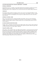
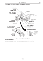
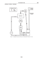
The hydraulic system consists of a pump, hoist cylinder, reservoir, filter, pilot valve, control valve, and
mechanically linked control lever located in the cab. A simplified functional diagram of the system is shown in
Figure 1.
1.
Hydraulic Pump.
The gear-driven pump is mounted directly to the vehicle PTO and supplies the system
with working pressure at 2500 psi (17237 kPa) maximum (with approximately 1200 rpm input speed
from PTO). There are two hydraulic ports at the opposite end of the pump from the gear spline. One port
is connected to the bottom of the hydraulic reservoir for oil supply to the pump. The other port is
connected to the control valve and supplies the pressure used to raise and lower the dump bed.
2.
Control Valve.
The control valve is a single spool type mounted on the right dump body subframe rail
about even with the forward-rear driving axle. The control spool is mechanically linked to the control
lever located in the cab. When the lever is operated, a rod connected to the control valve shifts the
control spool to another position. When the control lever in the cab is placed in the UP position, the
control valve routes hydraulic pressure to the hoist cylinder through the pilot valve. When the control
lever is placed in the DOWN position, the control valve provides a path for relief pressure from the pilot
valve back to the reservoir. The control valve contains a relief valve to protect the system from excess
pressure. The relief valve is set at 2000 psi (13790 kPa).
3.
Pilot Valve.
The pilot valve controls the flow rate of hydraulic fluid going to and coming from the hoist
cylinder. Flow rate of relief pressure can be adjusted.
4.
Hoist Cylinder.
The hoist cylinder is a three stage telescoping cylinder that extends about 130 in. It has
a pressure relief port at the top (end of smallest cylinder) that can be opened by hand and is used to
bleed air out of the system. The bottom of the hoist cylinder is attached to cross members located
between the dump body subframe rails. The top of the hoist cylinder is attached to the dump bed inside
the dog house near the top edge of the dump bed. Both attaching points are hinge pin arrangements so
the hoist cylinder can pivot as it is extended or retracted.
5.
Filter.
The system includes a filter located on the left dump body subframe rail. A 10 micron paper
element filters the hydraulic fluid before it reaches the reservoir (in the return pressure line from the
control valve). The filter has a gauge to indicate when the filter must be replaced.
6.
Reservoir.
The reservoir is an all steel container with a capacity of 20 gal. (75.7 L). Ports are provided
in the bottom of the reservoir for connecting a line to the hydraulic pump and connecting a return line
from the filter. The reservoir is mounted between the dump body subframe rails directly behind the cab.
The fill cap is also an air filter and breather for the reservoir. The breather for the reservoir must be kept
clean for proper hydraulic fluid circulation. Two sight glass bubbles are mounted on the side of the
reservoir for viewing fluid level.
7.
Electrical System.
The dump body has a marker lamp on each side, mounted at the top of the tailgate
support frame and one on each side of the tailgate on the back. It also has three marker lamps mounted
on a panel in the rear of the truck on the vehicle frame just below the tailgate. The electrical wiring for
the upper marker lamps is routed through the tailgate frame structure. All markers are connected to the
truck left rear tail/stop light.
TM 5-3805-274-13&P
0003
0003-2
Back to Top

