TM-5-3990-263-13-P - Page 18 of 728
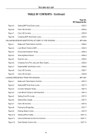
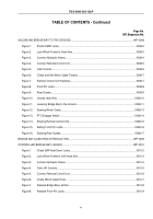
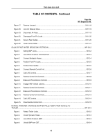
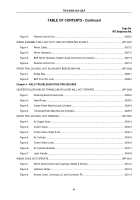
TABLE OF CONTENTS - Continued
Page No.
WP Sequence No.
Figure 9.
Remove Slack in Winch Cable.
............................................................................................
0010-9
Figure 10.
Open Rear Guides.
............................................................................................................
0010-10
Figure 11.
Brake and Transmission Controls.
.....................................................................................
0010-11
Figure 12.
Launch Bridge Bay.
............................................................................................................
0010-12
Figure 13.
Brake and Transmission Controls.
.....................................................................................
0010-13
Figure 14.
Stow Winch Cable Hook.
....................................................................................................
0010-14
Figure 15.
Cab LHS Controls.
.............................................................................................................
0010-15
Figure 16.
Stow Remote Control Unit.
.................................................................................................
0010-16
Figure 17.
Secure Front Pin Locks.
.....................................................................................................
0010-17
Figure 18.
Secure Rear Guides.
..........................................................................................................
0010-17
BRIDGE BAY FREE LAUNCH.
....................................................................................................................
WP 0011
Figure 1.
Cab LHS Controls.
...............................................................................................................
0011-3
Figure 2.
Check Front Pin Locks.
........................................................................................................
0011-4
Figure 3.
Connect Remote Control Unit.
.............................................................................................
0011-5
Figure 4.
Attach Lanyard to Air Release Valve.
...................................................................................
0011-6
Figure 5.
Connect Air Hose.
................................................................................................................
0011-7
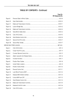
Figure 6.
Position Rear Guides.
..........................................................................................................
0011-8
Figure 7.
Center Roller Location.
.........................................................................................................
0011-9
Figure 8.
Position Center Roller.
.......................................................................................................
0011-10
Figure 9.
Remote Control Unit.
..........................................................................................................
0011-11
Figure 10.
Lock Winch Frame to BAP.
................................................................................................
0011-12
Figure 11.
Release IRB Foldlock Latches.
..........................................................................................
0011-13
Figure 12.
Unlock BAP from CBT.
.......................................................................................................
0011-13
Figure 13.
Stow Remote Control Unit.
.................................................................................................
0011-14
Figure 14.
Brake and Transmission Controls.
.....................................................................................
0011-15
Figure 15.
Release Front Pin Locks.
...................................................................................................
0011-16
Figure 16.
Cab LHS Controls.
.............................................................................................................
0011-17
TM 5-3990-263-13&P
vi
Back to Top

