TM-5-3990-263-13-P - Page 580 of 728
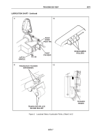
LUBRICATION CHART - Continued
Front Roller
GAA
•
S
(1 Fitting) (C)
(See View 14)
Rear Roller
GAA
•
S
(1 Fitting) (C)
(See View 15)
Hand Pump
OE/HDO
•
S
(See Note 8) (O)
(See View 7)
S
•
GAA
Center Roller
(1 Fitting) (C)
(See View 16)
S
•
OE/HDO
Winch Frame Locking
Levers & Release Pins
(See Note 4) (C)
(See View 13)
GAA
•
S
Loading Bar
(See Note 7) (C)
(See View 13)
Front Pin Lock
GAA
•
S
(2 Fittings) (C)
(See View 5)
S
•
GAA
Rear Roller
(1 Fitting) (C)
(See View 15)
S
•
GAA
Front Roller
(1 Fitting) (C)
(See View 14)
Winch Drum
GAA
•
S
(See Note 6) (C)
(See View 1)
S
•
GAA
Front Pin Lock
(2 Fittings) (C)
(See View 5)
Winch Case
OE/HDO
•
S
(See Note 8) (C, O)
(See View 2)
Transload Cylinder
GAA
•
S
Extensions
(C) (See View 11)
OE/HDO
•
S
Center Roller Cylinder Pins
(4 Surfaces) (C)
(See View 16)
S
•
GAA
Transload Cylinder
Extensions
(C) (See View 11)
Sheave Assembly Guide
CW
•
S
Surfaces & Roller Shafts
(See Note 6) (C)
(See View 1)
Transload Roller
CW
•
S
Bracket
(2 Surfaces) (C)
(See View 17)
S
•
CW
Transload Roller
Bracket
(2 Surfaces) (C)
(See View 17
S
•
GAA
Center Roller Track
(C) (See View 16)
S
•
CW
Winch Cable
(See Note 6) (C)
(See View 1)
Center Roller Track
GAA
•
S
(C) (See View 16)
Figure 2.
Semiannual Lubrication Intervals.
TM 5-3990-263-13&P
0070
0070-4
Back to Top


