TM-5-4210-249-13-P-2 - Page 1361 of 1452
TM 5-4210-249-13&P-2
0278-1
DRAFT
0278
FIELD LEVEL MAINTENANCE
PASSENGER SIDE AUXILIARY INLET AND DRIVER SIDE MAIN INLET BLEEDER VALVE REPLACEMENT
INITIAL SETUP:
REMOVAL
NOTE
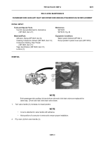
Both passenger side auxiliary inlet and driver side main inlet drain valves are replaced the
same way.
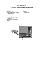
Driver side main inlet drain valve shown.
1.
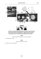
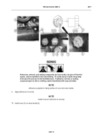
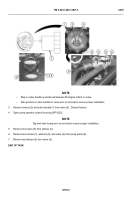
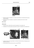
Turn valve handle (1) clockwise to closed position.
NOTE
•
Cover is attached to valve handle with adhesive.
•
Note position of cover prior to removal to ensure proper installation.
2.
Pry cover (2) from valve handle (1).
-
-
-
-
-
-
-
-
-
-
-
-
-
-
-
-
-
-
-
-
-
-
-
-
-
-
-
-
-
-
-
-
-
-
-
-
-
TFFT0309
Tools and Special Tools
Tool Kit, General Mechanic’s: Automotive
(WP 0622, Item 27)
Materials/Parts
Adhesive, Spray (WP 0625, Item 6)
Cleaning Compound, Solvent (WP 0625, Item 12)
Compound, Sealing, Pipe Thread
(WP 0625, Item 21)
Tags, Identification (WP 0625, Item 51)
Locknut (1)
References
WP 0325
WP 0615, Fig. 44
Equipment Conditions
Water system drained (WP 0041)
Pump operator’s panel cover open (WP 0019)
Back to Top

