TM-5-4210-249-13-P-3 - Page 1049 of 1488
TM 5-4210-249-13&P-3
0500-1
DRAFT
0500
FIELD LEVEL MAINTENANCE
CREW CAB ASSEMBLY REPLACEMENT
INITIAL SETUP:
REMOVAL
NOTE
•
Tag and mark connectors, wires, and hoses prior to removal to ensure proper installation.
•
Remove cable ties as required.
1.
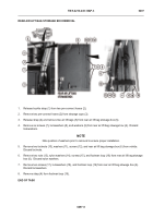
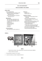
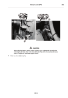
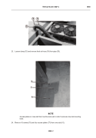
Disconnect three connectors (1), (2), and (3).
2.
Loosen two screws (4), and open compartment door (5).
-
-
-
-
-
-
-
-
-
-
-
-
-
-
-
-
-
-
-
-
-
-
-
-
-
-
-
-
-
-
-
-
-
-
-
-
-
TFFT01422
Tools and Special Tools
Crew Cab Lifting Fixture (WP 0622, Item 8)
Standard Automotive Tool Set (SATS),
(WP 0622, Item 25)
Tool Kit, General Mechanic’s: Automotive
(WP 0622, Item 27)
Materials/Parts
Tags, Identification (WP 0625, Item 51)
Ties, Cable, Plastic (WP 0625, Item 58)
Compound, Sealing (WP 0625, Item 17)
Lockwasher (1)
Preformed Packing (1)
Preformed Packing (1)
Lockwasher (1)
Locknut (2)
Locknut (2)
Personnel Required
MOS 63B Wheeled vehicle mechanic (3)
References
WP 0614, Fig. 6
WP 0615, Fig. 51, 164
Equipment Conditions
On-board tool mounting brackets removed
(WP 0528)
Crew cab seat removed (WP 0512)
Crew cab air conditioner coolant recovered
(TB 9-2320-279-13)
Batteries disconnected (TM 9-2320-325-14&P)
Air system drained (TM 9-2320-347-10)
Right side splash guard removed
(TM 9-2320-325-14&P)
Left side engine cover open and engine side
panel removed (TM 9-2320-325-14&P)
Driver side crew cab ladder removed (WP 0514)
Door switch removed (WP 0385)
Crew cab roof hatch opened (WP 0510)
Back to Top

