TM-5-5420-202-10 - Page 187 of 535
TM 5-5420-202-10
0029
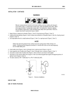
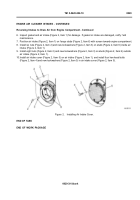
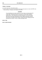
6. Inspect gasket and air intake (Figure 2, Item 1) for damage. If gasket or intake are damaged, notify f eld
maintenance.
7. Position air intake (Figure 2, Item 1) on f ange studs (Figure 2, Item 6) with screen toward engine compartment.
8. Install six nuts (Figure 2, Item 2) and new lockwashers (Figure 2, Item 3) on studs (Figure 2, Item 6) inside air
intake (Figure 2, Item 1).
9. Install eight nuts (Figure 2, Item 2) and new lockwashers (Figure 2, Item 3) on studs (Figure 2, Item 6) outside
air intake (Figure 2, Item 1).
10.Install air intake cover (Figure 2, Item 5) on air intake (Figure 2, Item 1), and install four hex-head bolts
(Figure 2, Item 4) and new lockwashers (Figure 2, Item 3) in air intake cover (Figure 2, Item 5).
Figure 2.
Installing Air Intake Cover.
END OF TASK
END OF WORK PACKAGE
0029-3/4 blank
ENGINE AIR CLEANER INTAKES -
CONTINUED
Reversing Intakes to Draw Air from Engine Compartment - Continued
Back to Top

