TM-5-5420-202-20-1 - Page 709 of 1020
TM
5-5420-202 -20-1
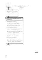
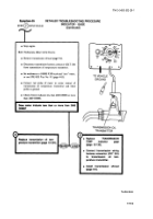
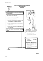
Symptom-35
DETAILED TROUBLESHOOTING PROCEDURE
INDICATOR - GAGE
(Continued)
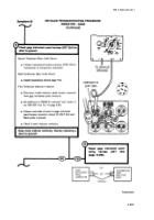
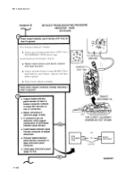
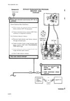
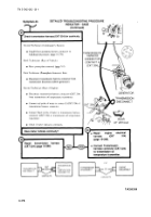
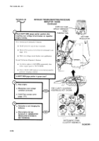
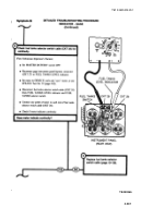
Check front accessory harness (CKT 324) for
continuity.
First Technician (Operator’s Station)
●
Connect basket-indicator panel harness connector to
gage instrument panel.
●
Install gage instrument panel (page 10-112).
Second Technician (Comn]ander’s Station)
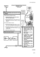
e Displace front mxessoryha rnessco nnector(CKT324)
from bulkhead disconnect s(page 10-269).
●
Connect redprobe ofmeter to contact D(CKT324)of
front accessory harness connector at basket disconnect
●
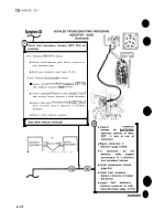
Connect black probe ofmeter tocontact E(CKT324)of
front accessory harness connector at bulkhead
disconnect.
●
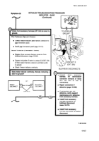
Check if meter indicates continuity,
Does meter indicate continuity?
■
t
,
CONTACTS
—
ly’’’’’’cT~”’””’’NEcTl
;ONTACT D
W (CKT 324 )
-
●
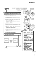
Inspect
accessory
harness
for
bentlbroken
connector contacts or loose
CKT
324
wire at rear of
connectors.
●
Repair connectors if
defective (page 10-298).
●
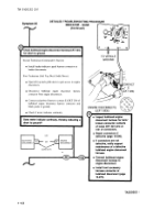
If
connectors
are
not
defective,
notify
support
maintenance of a defective
front accessory harness.
●
Install transmission shroud
(page 9-6).
●
Install front accessory
harness connector at basket
disconnect.
●
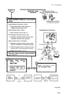
Install
front
accessory
harness connector at bulk-
head disconnect (page 10-270).
TA250357
●
4-472
Back to Top

