TM-5-5420-228-24 - Page 64 of 750
TM 5-5420-228-24
DETAILED
TROUBLESHOOTING
PROCEDURE
TROUBLESHOOTING
‘-
STEP
●
●
0
16
CONTINUED
USER GUIDE
(Continued)
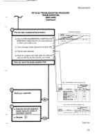
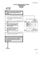
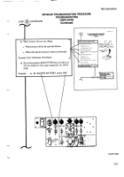
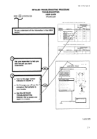
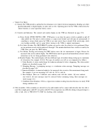
When a step tells you inspect
for bent/broken
connector
contacts
or loose
wires
at the
rear
of connectors
(or
repair
a harness)-a
circuit
diagram
is included.
1
This circuit
diagram
will show you which connectors
to
1
inspect/repair
and
where
they
are located.
“n
.
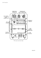
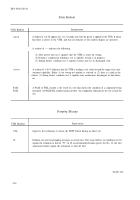
Indicates
amalepin,
single contact.
.
❑
Indicatesfemalesocket,
singlecontact.
1
,.
,.l,
).
:.
,mr.
1
*
.,
,“,
win.>
,4
~
muuO——
—m*.—
Ic———9l
-...—-
.
*
M.,,,
”
mm,”,
,.,,.,
m
.
“...-!
,
.r
1!$
-.--!.
.
!.1 .
.”!!
.!!”,
y&&
.
C...,t,.,
,
K,
,,”
-!,.!
hw”.”
.,.
=,,,
ha
C’C++NECIC+
.
cam,
rcd
F*
,,
””,.
,,.<-,.,
.-,.
4,X,
,,,’.
..””!.
,.
.,
.
...!-’”7
..,4.
..
,md
M..
*
.
$.!
)4.,,,”
,.,,,
”}
,.!!.,
0.
.
,h,
,(m””
,d.
.,.
1,
,’,
“).
.!,
*
---
!,.-*
.?
.M.
.OIm.
!”—
.
—elm
.,,
!.
,
,“
TA251331
2-31
2-31
Back to Top

