TM-55-2320-273-14 - Page 30 of 40
TM 55-2320-273-14
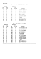
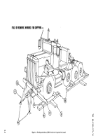
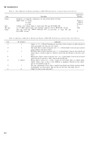
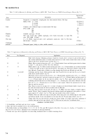
Table 7-1. Bill of Materials for Blocking and Tiedown of M915 FOV
Truck Tractor on CONUS General-Purpose Flatcar (Fig 7-1)
Approximate
Item
Description
Quantity
Nails
Lumber
Douglas-fir. or comparable; straight-grain, free from material defects; Fed Spec
MM-L-751H:
2-x 4-inch
108 linear ft
2-x 6-inch
77 linear ft
6-x 8-inch
12 linear ft
Common, steel; flathead, bright or cement-coated: Fed Spec
FF-N-105B: 12d
60
20d
224
40d
56
Thimbles
Standard, open-type, 5/8-inch
16
Clamps
Wire rope, U-bolt clips, saddled, single-grip, steel, Crosby heavy-duty, or equal; Fed
Spec FF-C-450D: 5/8-inch
48
Wire rope
6 x 19, IWRC; improved plow steel; preformed, regular-lay: table X, Fed Spec
RR-W-401C: 5/8-inch
120 feet
Cushioning
material
Waterproof paper, burlap, or other suitable material
as required
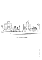
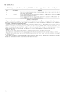
Table 7-2. Application of Matertials for Blocking and Tiedown of M915 FOV Truck Tractor on CONUS General-Purpose Flatcar (Fig 7-1)
Item
No. Required
A
B
c
D
E
F
G
H
J
12
12
1 ea item E
4
3
8
16
48
Application
Brake wheel clearance. Minimum clearance required is 6 inches above, in back of, and on both sides of
and 4 inches underneath wheel; 12 inches from end of car to load, which extends from center of brake
wheel to side of car; and 6 feet above car floor (fig 7- 1).
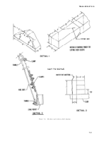
Blocks, Each to consist of one piece of 2- x 6- x 30-inch lumber, Locate on block against wheel as shown
in figure 7-1, and nail to car floor with seven 20d nails.
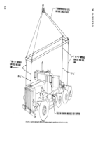
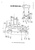
Blocks (detail 1, fig 7-2). Each to consist of one piece of 6- x 8- x 24-inch lumber, cut as shown in detail
1. Locate one block on top of each item B with 45: side against tire. Nail heel of block to item B with
three 40d nails. Toenail sides of block to car floor through item B with two 40d nails on each side.
Cushioning material. Locate bottom portion under item E and between tire and item E so as to extend 2
inches above item E (detail 2, fig 7-2).
Side blocks. Two to consist of one piece of 2- x 6- x 30-inch lumber and three pieces of 2- x 4- x 30-inch
lumber for the front tires, and two to consist of one piece of 2- x 6- x 90-inch lumber and three pieces of
2- x 4- x 90-inch lumber for the rear dual tires (detail 2, fig 7-2). Place against inside of front tires and
cushioning material and nail to car floor through 2- x 4- x 36-inch piece with twelve 20d nails. Nail the
other two 2- x 4- x 30-inch pieces to one below in same manner. Repeat this operation fro the other
front tire and the rear tires,
Brace. Each to consist of one piece of 2- x 6-inch x length-to-suit (about 60-inch) lumber. Locate one un-
der each axle between items E. Nail to car floor with ten 20d nails.
Wire rope. Each to consist of one piece 5/8-inch, 6 x 19, IWRC wire rope, length as required (approx-
imately 20 feet). Form a complete loop between tiedown shackle and appropriate stake pocket at a max-
imum angle of 45° (detail 3, fig 7-2). Wire rope ends should overlay about 24 inches.
Thimbles. Place one under wire rope at each place where rope passes over bottom edge of stake pocket
and tiedown shackle. Secure each thimble to wire rope with one 5/8-inch clamp (detail 3, fig
7-2).
Clamps. Place four on each item H at overlap area. Space clamps 3-1/2 inches apart with a minimum of
6 inches from ends of wire rope (detail 3, fig 7-2), Place one on each item J as indicated above.
GENERAL INSTRUCTIONS
1. Set handbrakes, and block and wire levers in place.
2. Place and wire-tie gearshift levers in the neutral position.
3. For further details, see General Rules 1, 2, 3, 4, 5, 14, 15, 19A, and 19B, Section I of the
Rules Governing the Loading of Commodities on
Open-Top Cars and Trailers,
published by the Association of American Railroads,
4. Tension wire rope with an applicable size come-along mechanical hoist or suitable tensioning device,
7-4
Back to Top

