TM-55-2320-280-14 - Page 37 of 44
25 August 1988
TM 55-2320-280-14
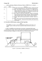
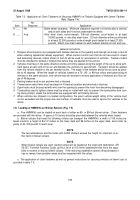
Table 7-2.
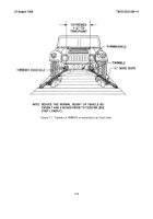
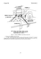
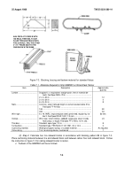
Application of Chain Tiedowns for Securing HMMWV on Flatcars Equipped with Center Tiedown
Rails (Figure 7-4)
Item
No.
Required
Application
A ........
NA
Brake wheel clearance.
Minimum clearance required is 6 inches above, behind,
and on both sides and 4 inches underneath the wheel.
B ........
4 ea
Alloy steel chain, extra-strength, 3/8-inch diameter, proof-tested to at least
18,000 pounds, or use alloy steel chain, 1/2-inch diameter either proof-tested
to at least 22,500 pounds or extra-strength proof-tested to at least 27,500
pounds.
Attach one chain tiedown to each tiedown shackle in front and rear.
General instructions
1.
Shippers should specify cars equipped with tiedown devices in the quantity and strength as shown in item B
when ordering specialized railway equipment.
When carriers furnish cars that do not have built-in chains
and tensioning devices, chains shown in item B will be used for securement of vehicles.
Tiedown chains
must be checked for twisted or kinked links before they are applied to the vehicle.
2.
Vehicles must face in the same direction and be uniformly spaced along the length of the car to allow suffi-
cient space at each end of the car and between the vehicles for securement.
Tiedowns should be applied
from the vehicle shackle to the car tiedown facility.
The angle of the tiedown should be as close as possi-
ble to 45 degrees.
When the length of vehicles loaded on a 75-, 85-, or 89-foot railcar precludes facing all
vehicles in the same direction, one vehicle may be reversed to ensure application of tiedowns at a floor an-
gle of 45 degrees.
3.
Parking brakes must be set and wire-tied or blocked.
4.
Transmission select lever must be placed in N (neutral) position and wire-tied or blocked.
5.
Open hooks must be secured with wire over the opening to prevent the hook from becoming disengaged.
6.
Turnbuckles used to tighten chains must be wired or locked with nuts to prevent the turnbuckles from turn-
ing during transit, unless the turnbuckles are equipped with self-locking devices.
7
.
When vehicles are shipped in a loaded configuration, the gross vehicle weight rating of the vehicle must
not be exceeded and the proper size and number of tiedowns must be used to secure the vehicles to the
railcar.
7-8.
Loading of HMMWVs on Bilevel Railcars (Fig. 7-5)
a.
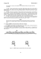
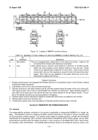
Five HMMWVs can be loaded on each deck of either an 85- or 89-foot bilevel railcar.
Chain tiedowns
are provided with the railcar.
A space of 10 inches should be provided between the vehicles when loaded.
b.
Bilevel railcars that meet the following criteria can transport the HMMWVs: a width of 109 inches be-
tween columns, a height of 84-1/2 inches on the lower deck and 96 inches on the upper deck, and a total ca-
pacity of 40, 000 pounds fin each level
NOTE
The two ambulances and the trucks with S-250 shelters exceed the height for shipment on ei-
ther deck of bilevel railcars.
NOTE
When bilevel railcars are used, loading ramps will be needed at the origin and destination. AR
55-357, Terminal Facilities Guide, gives a list of all US Army installations that have the capa-
bility to receive or ship by bilevel railcars.
If the receiving installation cannot offload because it
has no ramps, then portable ramps must be requested with the railcar.
c.
The application of chain tiedowns as well as general instructions for securing vehicles on bilevel cars is
provided in table 7-3.
7-6
Back to Top

