TM-9-1200-215-34-P - Page 259 of 266
TM 9–1200–215–34&P
ALPHABETICAL
INDEX – CONTINUED
INDEX–2
F
Fault Isolate LRU, 1–16
G
General Information, 1–1
General Troubleshooting and Maintenance, 1–15
Glossary, Glossary 1
H
How to use this manual, iv
I
Initial Fault Indication, 1–15
Inlet Valve Maintenance Instructions, 1–22
Introduction, 1–1
J
J5 Protective Cover Maintenance Instructions, 1–23
L
Location and Description of Major Components, 1–8
M
Maintenance Forms, Records, and Reports, 1–1
Major Components, Location and Description of, 1–8
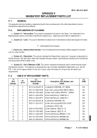
Mandatory Replacement Parts, F–1
Manual Troubleshooting – General, 3–3
N
Nomenclature Cross–Reference, 1–2
Nuclear Hardness, 1–3
P
Power Conditioning Unit (PCU), 6–1
CCA Maintenance Instructions, 6–12
Common Tools and Equipment, 6–1
Functional Description, 6–3
Handle Maintenance Instructions, 6–14
Maintenance Procedures, 6–8
Manual Troubleshooting, 6–3
Post–Maintenance Test, 6–8
Pre–Shop Analysis, 6–2
Repair Parts, Tools, Special Tools, Test,
Measurement and Diagnostic Equipment
(TMDE), and Support Equipment, 6–1
Service Upon Receipt, 6–1
Service Upon Receipt of Materiel, 6–1
Site and Shelter Requirements, 6–1
Top Cover Assembly Maintenance Instructions, 6–9
Troubleshooting Procedures, 6–8
Preparation for Storage or Shipment, 1–1
Prognostic/Diagnostic Interface Unit (PDIU), 4–1
Circuit Card Assemblies (CCAs) A2, A3, A4, and
A5, 4–13
Common Tools and Equipment, 4–1
Cover, Electrical Connector, 4–24
DC–DC Converter (Power Supply) (PS1), 4–15
Electrical Indicator Panel, 4–17
Electrical Indicator Panel, LEDs DS1 and DS2,
4–20
Functional Description, 4–3
Initial Fault Indication, 4–4
Maintenance Procedures, 4–6
Manual Troubleshooting, 4–3
Manual Troubleshooting Procedure, 4–5
Pre–shop Analysis, 4–2
Repair Parts, Tools, Special Tools, Test,
Measurement, and Diagnostic Equipment
(TMDE), and Support Equipment, 4–1
Service Upon Receipt, 4–1
Service Upon Receipt of Materiel, 4–1
Site and Shelter Requirement, 4–1
Spring Latch Assembly, 4–22
Top Cover Assembly and Bottom Cover, RFI/EMI
Contact Strip, 4–11
Top Cover Assembly, Bottom Cover, and Preformed
Packing, 4–7
Top Cover Assembly, Neoprene Rubber Strip(s),
4–9
Purge LRU, 1–18
R
References, A–1
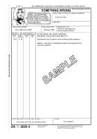
Reporting Equipment Improvement
Recommendations (EIR), 1–2
Back to Top


