TM-9-1240-400-34-P - Page 14 of 344
TM 9-1240-400-34&P
1-9.
LOCATION AND DESCRIPTION OF MAJOR COMPONENTS (CONT).
c.
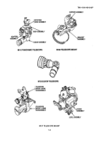
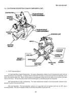
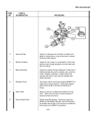
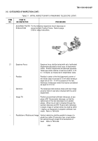
M137 Telescope Mount.
(1)
Telescope Mount Upper Subassembly.
The upper subassembly contains most of the electrical system and the
mounting surface for the telescope.
A variable resistor knob turns the power on and off and controls the brightness of the
LED in the extension light only.
Switch controls power to the telescope contact and to the LEDs for the counters and level
vials on the mount.
The top mounting surface has two locating pins to accurately position the telescope.
(2)
Telescope Mount Lower Subassembly.
The lower subassembly includes a mounting bracket, elevation knob,
elevation counter, and cross-level knob.
(3)
Level Assembly.
The level assembly consists of a cross-level vial, an elevation level vial, an LED, and a
mounting bracket.
The mount is leveled visually by centering the bubble in each level vial.
1-6
Back to Top

