TM-9-1290-262-24-P - Page 98 of 192
ARMY TM 9-1290-262-24&P
MARINE CORPS TM 00476C-24&P
AIR FORCE TO 49A7-3-72/74
4-4. TEST AND ADJUSTMENT PROCEDURES (cont).
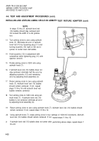
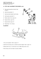
PARALLAX OF OBJECTIVE ASSEMBLY
1
2
3
4
5
6
7
Direct aiming circle (1) line-of-sight into
collimator (2).
Adjust collimator (2) for a distance of 50 yd
(46 m).
Check parallax between image of collima-
tor reticle and aiming circle reticle at the
center of field of view. Parallax must not
exceed 0.3 roil. Parallax between tele-
scope reticle and projector collimator shall
be near zero at 50 yd (46 m), and shall not
exceed 0.3 mils over a range of 30 to 150
yd (27 to 137 m).
Sight through aiming circle eyepiece at
normal eye distance. Move your head 1/4
inch from side to side and up and down. If
image of collimator reticle appears to move
with respect to aiming circle reticle, paral-
Iax is present. Amount of parallax is indi-
cated against markings on collimator reti-
cle.
Screw objective assembly (3) in or out as
required. Repeat step 4.
If parallax cannot be eliminated, replace
objective assembly. Repeat steps 4 and 5
until parallax is eliminated.
Spot seal edge of objective assembly to
telescope body in two places with sealing
compound (item 8, appx D).
4-24
Back to Top


