TM-9-1290-365-24-P - Page 15 of 334
ARMY TM 9-1294-365-24&P
LIST OF ILLUSTRATIONS
Figure
Title
Page
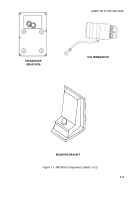
1-1
M93 MVS Components .
.................................................................................
1-3
1-2
M93 MVS Interconnection.
.............................................................................
1-12
1-3
Transceiver Assy Simplified Block Diagram.
..................................................
1-14
1-4
Doppler Amplifier Module Simplified Block Diagram.
.....................................
1-15
1-5
Power Supply Module Simplified Block Diagram .
..........................................
1-16
1-6
MVP Simplified Block Diagram.
......................................................................
1-18
1-7
Transceiver RF Section (Part of Transceiver Assy, P/N
13002074) .
..................................................................................................
1-21
1-8
Transceiver Back Cover Assembly (Part of Transceiver Assy, P/N
13002074).
.....................................................................................................
1-22
1-9
Mounting Bracket Assy, P/N 12979003.
......................................................
1-23
1-10
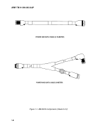
Power and Data Cables .
................................................................................
1-24
1-11
1553 Termination, P/N 12979006 .
.................................................................
1-25
3-1
Power and Data Cable (0.75-Meter), P/N 12979004 .
....................................
3-11
3-2
Power and Data Cable (0.75-Meter), P/N 12979004, Connector
Pin Locations.
..............................................................................................
3-12
3-3
Power and Data Cable (0.75-Meter), P/N 12979004, Wiring Diagram.
..........
3-12
3-4
Power and Data Cable (5-Meter), P/N 12991852 .
.........................................
3-16
3-5
Power and Data Cable Test Setup.
................................................................
3-18
3-6
Power and Data Cable Tester, P/N AY6707984-0, Schematic Diagram.
.......
3-19
3-7
Power and Data Cable (5-Meter), P/N 12991852, Wiring Diagram.
...............
3-21
3-8
Power and Data Cable (5-Meter), P/N 12991852, Connector Pin
Locations.
....................................................................................................
3-21
3-9
1553 Stub (Part of Power and Data Cable (5-Meter), P/N 12991852).
..........
3-23
3-10
1553 Termination, P/N 12979006 .
.................................................................
3-28
3-11
Bracket Assembly, P/N 12979003.
.................................................................
3-31
3-12
Bracket Assembly, P/N 12979003, Removal and Installation .
.......................
3-32
4-1
M93 MVS Installation .
....................................................................................
4-2
C-1
M93 Muzzle Velocity System, P/N 13002073 .
...............................................
C1-1
C-2
Transceiver Assy, P/N 13002074.
..................................................................
C2-1
C-3
Power Supply Module, P/N AY6707291-0 .
....................................................
C3-1
C-4
Power Supply CCA, P/N 6707290-0 .
.............................................................
C4-1
C-5
Doppler Amplifier CCA, P/N AY6706566-0 .
...................................................
C5-1
C-6
EMI Filter Module, P/N AY6707289-1 .
...........................................................
C6-1
C-7
Muzzle Velocity Process, P/N AY6707288-3 .
................................................
C7-1
C-8
Bracket Assembly, P/N 12979003 .
................................................................
C8-1
C-9
Power and Data Cable (0.75 Meter), P/N 12979004 .
....................................
C9-1
C-10
Power and Data Cable (5 Meter), P/N 12991852 .
.........................................
C10-1
C-11
Special Support Equipment.
...........................................................................
C11-1
Change 1
v
Back to Top

