TM-9-2320-209-20-2-1 - Page 75 of 645
TM 9-2320-209-20-2-1
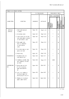
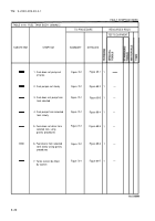
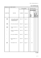
TABLE 6-26. HOT WATER HEATER
TS PROCEDURES
RESOURCES REQ'D
TEST EQUIPMENT
SUBSYSTEM
SYMPTOM
SUMMARY
DETAILED
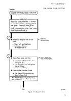
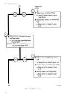
1. Cool or cold air at outlets
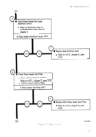
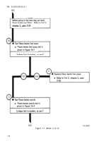
Figure 92-1
Figure 91-1
1
—
after engine has reached
operating temperature
2. No air flow at heat outlet
Figure 92-1
Figure 91-2
1
—
3. Blower motor does not
Figure 92-1
Figure 91-3
1
—
work
—
4. Blower motor operates on
Figure 92-1
Figure 91-4
1
—
HI only
—
5. No air flow at defroster
Figure 92-1
Figure 91-5
1
.
—
6. Blower operates in LO
Figure 92-1
Figure 91-6
1
—
only
7. Heat output too low
Figure 92-1
Figure 91-7
1
.
6-3 1
Back to Top

