TM-9-2320-260-20 - Page 729 of 1337
TM 9-2320-260-20
9-18. POWER STEERING PUMP HOSES REPLACEMENT
THIS TASK COVERS:
a. Removal
b. Installation
INITIAL SETUP
APPLICABLE MODELS
EQUIPMENT CONDITION
All
• Parking brake set (TM 9-2320-260-10).
MATERIALS/PARTS
•
Hood raised and secured (TM 9-2320-260-10).
• Power steering pump reservoir drained
Cap and plug set (Appendix C, Item 9)
(TM 9-2320-260-10).
Antiseize tape (Appendix C, Item 30)
• Power steering gear stone shield removed
REFERENCES (TM]
(para. 11-26).
LO 9-2320-260-12
TM 9-2320-260-10
TM 9-2320-260-20P
a. Removal
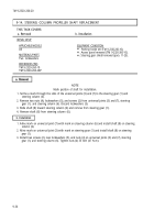
1. Remove nut (11), screw (9), and strap (10) from pressure hose (8) and return hose (3).
2. Loosen and slide clamp (2) down return hose (3).
CAUTION
Cap or plug all open hydraulic lines, fittings, and ports to prevent
dirt contamination from entering system. Failure to do so may
result in damage to internal components.
NOTE
• Tag hydraulic lines and ports for installation.
• Have drainage container ready to catch hydraulic fluid.
3. Disconnect return tube (5) from power steering gear (6).
4. Disconnect return hose (3) from power steering pump (1).
5. Remove clamps (2) and (4) from return hose (3) and tube (5), and separate return hose (3) from
tube (5).
6. Disconnect pressure hose (8) from power steering pump (1).
7. Disconnect pressure hose (8) from elbow (7).
b. Installation
NOTE
Protective caps and plugs must be removed from lines, fittings,
and ports before installation.
1. Apply antiseize tape to male threads of tube (5), elbow (7), and pressure hose (8).
2. Install pressure hose (8) on elbow (7).
3. Install pressure hose (8) on power steering pump (1).
4. Slide clamps (2) and (4) on return hose (3).
5. Install tube (5) in return hose (3) and tighten clamp (4) around connection of return hose (3)
and tube (5).
6. Install tube (5) on power steering gear (6).
9-44
Back to Top


