TM-9-2320-260-34-1 - Page 388 of 657
TM 9-2320-260-34-1
5-25. FUEL PUMP CALIBRATION
THIS TASK COVERS:
a. Throttle Shaft Cover Removal
h.
b. Mounting Pump to Test Stand
i.
c.
Fuel Pump Run-In
j
d. Testing Pump Seals for Leaks
k.
e.
Testing Governor Cutoff RPM
1.
f. Testing and Adjusting Throttle Leakage
m.
g. Testing and Adjusting Idle Speed
n.
Checking and Adjusting Throttle Lever Travel
Testing and Adjusting Pump Main Pressure
Testing and Adjusting Fuel Pressure
Testing and Adjusting Governor Fuel Pressure
Checking and Adjusting Governor Weight Pressure
Testing and Adjusting Idle Speed (VS Governor Only)
Shutdown and Removal from Test Stand
INITIAL SETUP
APPLICABLE MODELS
All
SPECIAL TOOLS
Spring pack adjusting tool
(Appendix B, Item 100)
Travel template (Appendix B, Item 101)
Shaft installation tool
(Appendix B, Item 104)
Gear pump block plate
(Appendix B, Item 103)
MATERIALS/PARTS
Ball bearing (Appendix D, Item 3)
Two screws (Appendix D, Item 378)
Lockwasher (Appendix D, Item 225)
GAA grease (Appendix C, Item 14)
Lubricating oil (Appendix C, Item 21)
Calibrating oil (Appendix C, Item 5)
Antiseize tape (Appendix C, Item 50)
REFERENCES (TM)
TM 9-2320-260-34P-1
TOOLS
EQUIPMENT CONDITION
General mechanic’s tool kit
Fuel pump removed (para. 5-13).
(Appendix B, Item 1)
Manual fuel pump shutoff valve removed
TEST EQUIPMENT
(para. 5-15).
Fuel injection pump tester stand
(Appendix B, Item 88)
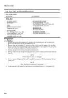
a. Throttle Shaft Cover Removal
1.
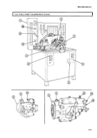
Remove nut (7), lockwasher (6), washer (5), screw (9), washer (8), and lever (4) from accelerator
shaft (2). Discard lockwasher (6).
NOTE
Perform step 2 if throttle shaft cover has not been removed.
2. Remove two drive pins (10) and cover (3) from fuel pump (1). Discard drive pins (10).
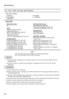
b. Mounting Pump to Test Stand
1. Install adapter ring (14) on adapter bracket (13) with four washers (12) and screws (11).
2. Install adapter bracket (13) on test stand (20) with clamp bar (18).
3. Install fuel pump (1) on adapter bracket (13) and adapter ring (14) with four washers (17) and
screws (16).
4. Position coupling drive (19) in test stand drive coupling (15).
5. Slide fuel pump (1) forward to engage coupling drive (19) with test stand drive coupling (15) on test
stand (20).
5-68
Back to Top

