TM-9-2320-260-34-2 - Page 11 of 863
TM 9-2320-260-34-2
I
12-6. POWER STEERING TEST AND ADJUSTMENT
THIS TASK COVERS:
a. Steering Pump Test Equipment Installation
e. Poppet Adjustment
b. Steering Pump Pressure Test
f. Sector Shaft Adjustment
c. Steering Pump Flow Test
g. Steering Pump Test Equipment Removal
d. Steering Gear Internal Leakage Test
INITIAL SETUP
APPLICABLE MODELS
All
TOOLS
General mechanic’s tool kit
(Appendix B, Item 1)
Torque wrench, 3/8-in. dr.
(Appendix B, Item 4)
TEST EQUIPMENT
Power steering test set (Appendix B, Item 145)
Flowmeter (Appendix B, Item 146)
Thermometer (Appendix B, Item 147)
MATERIALS/PARTS
Cap and plug set (Appendix C, Item 6)
REFERENCES (TM)
LO 9-2320-260-12
TM 9-2320-260-10
TM 9-2320-260-20
TM 9-2320-260-34P-1
EQUIPMENT CONDITION
Steering gear shield removed (TM 9-2320-260-20).
GENERAL SAFETY INSTRUCTIONS
All personnel must be clear of vehicle when vehicle
engine is running.
WARNING
All personnel must be clear of vehicle when vehicle engine is
running. Vehicle could suddenly move and cause injury to
personnel.
NOTE
Do not begin this procedure before performing all preliminary
maintenance checks (para. 12-3).
a. Steering Pump Test Equipment Installation
CAUTION
Clean area around hoses and lines before removal to prevent
entry of dirt. Damage will occur if dirt or dust enters the
steering system.
Cap or plug all openings immediately after disconnecting lines
and hoses to prevent contamination. Remove caps or plugs
prior to connection. Failure to do so may result in damage to
equipment.
NOTE
Have drainage container ready to catch power steering fluid.
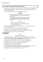
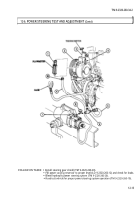
1. Remove pressure hose (5) from elbow (8).
2. Install load shutoff valve (7) on elbow (8).
3. Install tee (6) on load shutoff valve (7).
4. Install pressure hose (5) and gage on tee (6).
12-6
Back to Top

