TM-9-2320-260-34-2 - Page 257 of 863
TM 9-2320-260-34-2
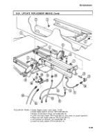
15-50. LIFTGATE REPLACEMENT (M820A2)
THIS TASK COVERS:
a. Removal
b. Installation
INITIAL SETUP
APPLICABLE MODELS
M820A2
TOOLS
General mechanic’s tool kit
(Appendix B, Item 1)
Hydraulic jack
MATERIALS/PARTS
Cap and plug set (Appendix C, Item 6)
Antiseize tape (Appendix C, Item 50)
REFERENCES (TM)
LO 9-2320-260-12
TM 9-2320-260-10
TM 9-2320-260-20
TM 9-2320-260-34P-2
EQUIPMENT CONDITION
●
Hydraulic oil reservoir drained
(LO 9-2320-260-12).
●
Van body ladders removed (TM 9-2320-260-10).
●
Liftgate platform opened but not lowered
(TM 9-2320-260-10).
●
Liftgate platform controls removed
(TM 9-2320-260-20).
●
Liftgate control valve removed (para. 15-58).
GENERAL SAFETY INSTRUCTIONS
●
All personnel must stand clear during lifting
operations.
Ensure lifting capacity is greater than weight
of liftgate.
CAUTION
●
Clean area around hoses and lines before removal to prevent
entry of dirt. Damage will occur if dirt or dust enters system.
●
Cap or plug all openings immediately after disconnecting lines
and hoses to prevent contamination.
NOTE
●
Tag all hydraulic lines and fittings for installation.
●
Have drainage container ready to catch oil.
1. Remove hydraulic hoses (12) and (13) from two elbows (6).
2. Remove two elbows (6) from closing cylinder (5).
3. Remove hydraulic hoses (11) and (14) from adapter (10) and restrictor (22).
4. Remove adapter (10), elbow (9), nipple (8), and restrictor (22) from cylinder (4).
5. Remove hydraulic hoses (15) and (16) from elbows (20).
6. Remove check valve (19) and two connectors (18) from closing cylinder (17).
7. Center hydraulic jack under liftgate (1) and raise in place.
8. Remove twelve nuts (3) and screws (7) from main frame (21) and vehicle frame (2).
●
All personnel must stand clear during Iifting operations.
A swinging or shifting load may cause injury to personnel.
●
Ensure lifting capacity is greater than weight (500 lb (227 kg))
of liftgate. Failure to do so may result in injury to personnel or
damage to equipment.
15-196
Back to Top


